


Cooling water pumps for power plant condenser cooling systems are large flow-rate, low- to medium-head units that operate at low rotational speeds. For these pumps' parameters, a typical hydraulic design stage configuration, optimal from the efficiency point of view, is either a mixed-flow or axial-flow single stage unit.
These pumps are developed and delivered by several leading pump manufacturing companies and are operational worldwide in both fossil-fuel and nuclear power stations (in the latter case, in a secondary cooling loop).
The use of computer-aided design (CAD) based geometry modellers in the industry (see Reference 4) and computational fluid dynamics (CFD) (see Reference 5 and Reference 6) allows for the definition and optimization of the shapes of the through-flow channels and blades. Designers arrive at design solutions that have improved performance features, when compared to machines designed using earlier and, to a large extent, test-based methods outlined in References 1 and 2.
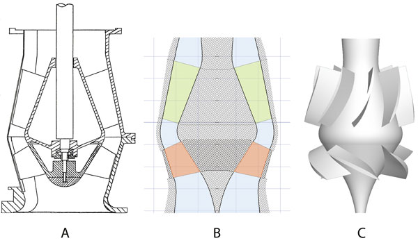 Figure 1. Case 1 pump's digital design model (Graphics courtesy of Denus TurboDesign Solutions)
Computer-Aided Engineering
To satisfy the operational requirements of cooling water pumps and ensure that the high efficiency values of these pumps, their hydraulic layout results in the design solutions in the high specific speed mixed-flow and axial-flow ranges. Early generations of these pumps were designed using basic engineering approaches, which combined one-dimensional modeling of flow properties with the empirically derived design factors and coefficients.
The inaccuracy of these methods and the limited validity range of the empirically derived design factors had to be compensated for by the cost- and time-intensive test-bed optimization effort at the manufacturers' sites to achieve performance goals and meet project specifications.
The development of advanced, computer-aided engineering (CAE) and, particularly, the numerical flow simulation technologies makes it possible for manufacturers to further develop the existing pump ranges and optimize them for each application, including the design solutions for large capacity water cooling pumps.
Pump Research Data
Research on the pumps' internal flow patterns at design and off-design conditions—such as those reported in Reference 8 and Reference 9—provides pump designers with knowledge of the flow phenomena, which can be correlated to the measured performance. For the design process, the flow simulation technology must employ tools that are capable of predicting measured performance curve and, flow conditions and phenomena during the design phase, before the pump is manufactured and tested.
A study was conducted to validate a CFD program when applied to a real, mixed-flow pump stage, with the impeller and diffuser assembly typical for large capacity cooling water pumps with the specific speed of 6,350 (U.S. units). Pump Case 1 based on Reference 8 data and shown in Figure 1, was selected for this analysis. It represented a research pump designed by the National Engineering Laboratory (NEL), East Kilbride, Scotland and experimentally investigated at the Strathclyde University, Glasgow.
This research resulted in the pump's overall performance characteristics (for example, Q-H and Qη curves) as well as an assembly of data on the internal velocity distributions and flow patterns which, using the Laser Doppler Anemometry (LDA), were measured at several flow rates. A distinct performance feature of this stage is its Q-H curve instability at flows below Q = 0.74 QBEP, (see Figure 4).
The cross-sectional drawing is shown in Figure 1A. The data given in Reference 7, providing a complete geometrical definition of all the components in terms of their surfaces points (x, y, z coordinates), were used to develop the digital design model, which is the integral part of a design package applicable for pump and turbomachinery design.
Both the meridional flow path, Figure 1B, and the fully 3D digital model of the pump stage, Figure 1C, were created to enable the performance prediction and the flow analysis process. Figure 2A shows the grid of H-type, which was created for this case using a CFD mesh generating code to facilitate the Navier-Stokes CFD solution on this mesh.
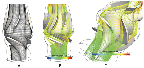 Figure 2. Case 1 pump's CFD solutions at BEP
Figures 2B and 2C demonstrate sample outputs in terms of the flow-field and the velocity distribution at BEP conditions.
Considering the off-design operation, Figure 3A shows regions of flow recirculation in the inlet part of the impeller passage—identified by LDA—located at the upper part of the through-flow channel, close to the outer shroud contour. The flow recirculation was captured at Q = 0.46 QBEP,.
Engineers compared the experimental findings of Figure 3A with the CFD solutions (see Figure 3B) derived for the same geometry and flow conditions in the instability region (which are also shown as the superposition onto the experimental data). The CFD was able to capture the complex internal flow recirculation pattern as far as its location, size and direction at these partial load conditions.
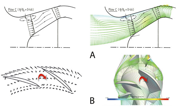 Figure 3. Case 1 pump's CFD solutions at the partial-load operation
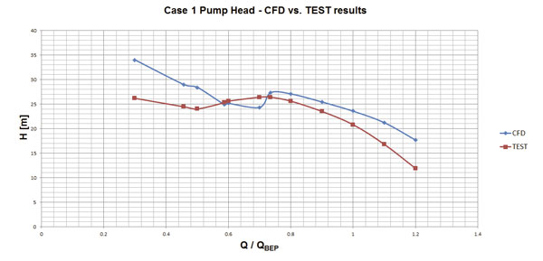 Figure 4. Case 1 pump's Q-H performance—CFD vs. tested
For Pump Case 1 (NEL), the measured global pump characteristic, Q-H, Figure 4, showed a region of positive slope (partial-load instability) which was correctly predicted using CFD, including the point of stalled conditions. Figure 4 shows raw CFD results from the Navier-Stokes solution that used mixing plane for the impeller and vane diffuser assembly CFD analysis. No corrections were applied, due to the inherent loss components while generating Figure 4, which explains the discrepancy between the head values measured (as tested) and those numerically obtained (CFD).
- Pfleiderer, C. Kreiselpumpen fuer Fluessigkeiten und Gaese", 5th ed., Springer, Berlin, 1961.
- Stepanoff, A. Axial and Radial Flow Pumps, 2nd ed., Wiley & Sons, New York, 1957.
- Rosemann, P. "Special Technical Problems of a Large Pump Project," (in German), KSB Technical Report no. 16, 1973.
- Favre, J.N. "Development of a Tool to Reduce the Design Time and to Improve the Radial or Mixed-Flow Pump Impeller Performance," ASME FED-Vol.222, 1995.
- Denus, C.K., et al. "A Study in Design and CFD Analysis of a Mixed-Flow Pump Impeller," ASME FEDSM 1999, San Francisco, Calif., 1999.
- Denus, C.K., et al. "Hydraulic Development of a Centrifugal Pump Impeller Using the AGILE Turbomachinery Design System," TASK Quarterly 6, No.1, 2002.
- Nagahara, T. et al. "Investigation of the Flow Field in a Multistage Pump by Using LES," ASME FEDSM2005, Paper no. 77319, Houston, Texas, 2005.
- Carey, C. et al. "Studies of the Flow of Air in a Model Mixed-Flow Pump by LDA," NEL Rep. 698 and NEL Rep. 699, East Kilbride, 1985.
- Goto, A. "Study of Internal Flows in a Mixed-Flow Pump Impeller at Various Tip Clearances Using 3D Viscous Flow Computations," ASME Paper 90-GT-36, 1990.