


Process control through traditional adjustable speed drives (ASDs) with centrifugal pumps has an inherent problem of attempting to use a linear equation to solve a non-linear problem. Common ASD controller software provides an estimated speed to achieve a desired set point. But when the target speed is reached with this method, the set point is not available because the answer is on an unknown non-linear curve.
The software must again guess the speed and decrease the error. This process continues until a reasonable deviation from the set point is met. If one aspect of the system curve changes, the whole process must be restarted. Searching for the speed costs energy, even on a single machine.
On a system with multiple machines operating either in series or in parallel, a second and more serious problem occurs\'97balancing the load. Even if the machines are built to the same specifications, differences in motor performance, impeller clearances and other mechanical design issues will change a specific pump's speed.
Conventional frequency control operates multiple devices at the same speed. In parallel operation, the pump with the greatest pressure capture most of the output and corresponding amperage while the other pumps use a fairly high amount of power and add little to the total output. There is no way to balance a load using frequency directly, because the smallest of physical differences will cause a shift in power to the device with the highest pressure.
Balancing the Set Points
Specialized balancing algorithms start with a fixed linear pump curve number. If the output electrical current is less than the number, the frequency is increased. If the output current is greater than the number, the frequency is decreased.
On centrifugal pumps, the frequency in Hertz turns into rpm to meet the amp draw. Amp draw is linear to both pressure and flow, and non-linear to speed. This is in contrast to the balancing algorithm, which directly controls power to meet pressure or flow.
Consider the pump affinity laws, where the diameter of the impeller is held constant:
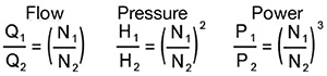
Q = flow
H = pressure
P = power
N = speed of impeller
The fixed linear pump curve number is a percentage of available amps of power of a specific ASD. When the motor and pump are set up, the motor's full-load amps are entered into the drive. The ASD temporarily sets the maximum variable to the entered motor amps divided by the ASD full output amps. The maximum can be adjusted to achieve the desired set point for flow or pressure.
The minimum value is set to find the lower limit, or motor stall point. In multiple-pump systems, each machine repeats the same operational set points. The software then creates a linear pump curve where each pump will run at the required power to match other pumps' set points.
Simplifying Control
If controlled from a common external analog signal, a minimum value of 0 percent will cause all the pumps to run at the minimum set point. The same is true at a value of 100 percent, where pumps will run at their maximums. Each change in set point will affect linear flows and pressures and non-linear frequencies and amp draws.
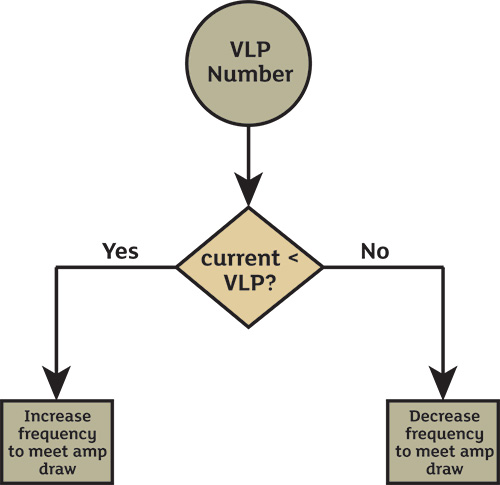 Figure 1. Determining how to meet amp draw based on virtual linear pumps (VLPs)(Courtesy of Toshiba)
When the frequency is changed in standard ASDs, the output is non-linear. Energy is wasted searching to find the appropriate speed to satisfy the control loop. Because the software produces a virtual linear performance curve, the first calculation from an external controller will most likely be the most accurate calculation. The software changes the power of the motor to produce the desired pressure or flow. No time or energy is wasted accelerating and decelerating.
Each ASD can calculate what speed to run at in order to independently hold the set point. This would be impossible for separate drives running speed control because each drive would fight the other with hunting errors until the whole system became unbalanced. Because the software provides a virtual line of performance, each ASD can select an individual point that represents exactly the same pressure at flow point as every other ASD. So, the overall control system is greatly simplified.
Balancing Multiple Pumps
Each pump is tuned during commissioning to produce a specific result, such as a flow rate or pressure at both minimum and maximum values. Each motor/pump combination is unique and requires slightly different frequencies and power requirements at both end points and every point in between. Because all ASDs share the same common reference signal, they can independently calculate the power needed to match the flow/pressure of all the pumps online. In a series operation, this effect is even more pronounced. If series pumps are run at the same speed, they have different velocities. This is analogous to a traffic jam on an expressway where the cars are stopping and starting. With a balancing software, the "cars" are all moving at the same velocity. Without this software, the difference in velocities between pumps can result in pressure waves that cause mechanical stress and wasted power.