


Q. How is motor efficiency impacted when the motor is controlled by a variable frequency drive (VFD)?
A. Typical motor losses for a 4-pole 15 horsepower (hp) motor are analyzed in Table 6.3. End users are typically aware of the nominal motor efficiency that is listed on the pump nameplate and represented in this table; however, motor efficiency does change as speed and torque change and is also affected by voltage harmonics present in the VFD output. The magnitude of losses due to voltage harmonics will vary with the
motor design.
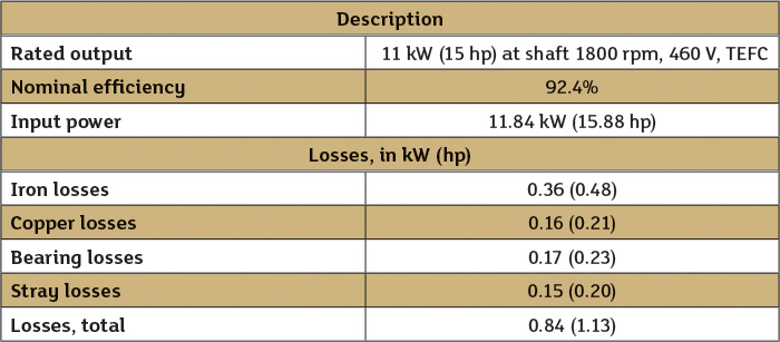 Table 6.3. The energy cost balance sheet for the operating system
In most cases, these additional losses will be relatively small with a modern VFD and motor combination, and the additional losses within the motor at full speed and full power will be
less than 5 percent of the total motor losses. The distribution of losses in a motor is specific to a particular type of motor and power drive system.
Copper losses will reduce with load, while bearing and windage losses reduce with speed. In a cage induction motor, iron losses stay constant with constant flux, but can be reduced with more sophisticated flux control.
As mentioned previously, the efficiency of a motor will change when operated at reduced speed or torque. Figure 6.4 shows typical efficiency/speed curves for a VFD-driven, high-efficiency-type motor with a nominal efficiency of 95 percent at different percentage torque loads (T/Tn) and speeds. Figure 6.4 shows a reduced efficiency at reduced torque, independent of speed, and when speed is reduced efficiency is reduced additionally.
When VFDs are applied to control a pump, it is typically done to match the pump hydraulics to the system, which eliminates throttling of unnecessary head or bypassing of unnecessary pump flow. These improvements to overall system efficiency can greatly outweigh the reduction in motor efficiency.
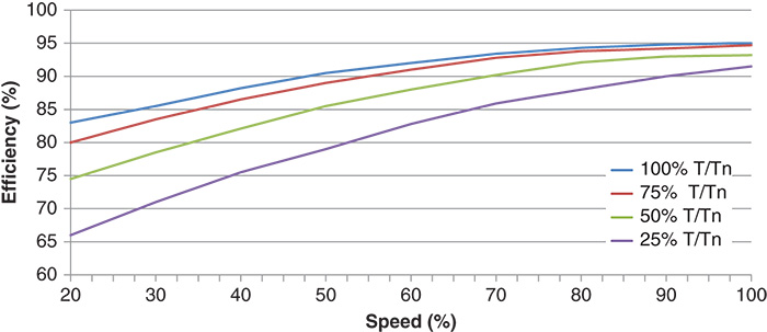 Figure 6.4. Motor efficiency versus speed (nominal 95% efficient motor) (Courtesy of Hydraulic Institute)
For more information on applying VFDs to pump motors, refer to HI’s newly published Application Guideline for Variable Speed Pumping at www.pumps.org.
Q. I have heard the terms constant and variable torque pumping applications and that they impact applying variable speed pumping. What do these terms mean and how do they impact variable speed pumping?
A. One characteristic of a variable torque load is that the torque loading is a function of speed, and this type of load requires less torque at lower speeds than constant torque loads. Conversely, one characteristic of a constant torque load is that the torque loading is not dependent on speed and will require a higher torque at reduced speed than a variable torque load.
- Rotodynamic pumps are variable torque loads due to the nature of the pump affinity rules, whereby, head changes proportional to the square of the speed change.
- Positive displacement pumps are constant torque loads because the head they are capable of pumping against is independent of speed. Positive displacement pumps deliver a volume of fluid for every revolution of the shaft, so a reduced speed will directly impact the flow delivered, but it has no direct impact on the differential head or pressure the pump will deliver flow against.
When selecting a VFD for a rotodynamic pump application, many manufacturers recommend a variable torque or standard-duty-rated VFD. This labeling is commonly referenced for the overload capacity of the drive. An industry standard for a variable torque (VT) overload is 110 percent for 60 seconds. When selecting a VFD for a positive displacement pump application, the VFD manufacturer will recommend a drive specific to that application that is suitable for the constant torque (CT) load. An industry standard for a CT overload is 150 percent for 60 seconds.
For more information on applying VFDs in pumping applications refer to HI’s guidebook Variable Frequency Drives: Guidelines for Application, Installation and Troubleshooting at www.pumps.org.
Q. Can I have my centrifugal pump tested inclusive of the motor and VFD?
A. The American National Standard for testing of centrifugal pumps is ANSI/HI 14.6 Rotodynamic Pumps for Hydraulic Performance Acceptance Tests. Per this standard, generating a pump curve requires the measurement of head, rate of flow and power. The efficiency of the pump can be calculated from this information. Historically, the power and efficiency shown on the pump curve and what may be guaranteed for acceptance has been respective to the pump shaft input power. Thus the efficiency published is only that of the pump, not of any other component. From a testing standpoint, the most accurate way to obtain the pump input power data is by direct measurement of the shaft torque and rpm. This is typically done using a torque transducer between the pump and driver and a tachometer. The standard does provide provisions for guaranteeing the combined pump and motor unit, combined efficiency or the maximum motor input power.
To have your extended pump product tested inclusive of the motor and VFD, you can typically work with the pump manufacturer or independent laboratory. One method that may be specified is a string test using the complete assembly with VFD, motor, gearbox, belt drive, etc.
The accuracy of this test in determining pump input power will be lower than when the pump is tested by itself, but gives the added benefit of measuring total power consumed by the extended product. In this instance, the power measured is the input power to the motor or VFD inclusive of all losses downstream.
The input power to the pump shaft can then be calculated by taking into account the published motor and drive efficiencies. Since these efficiencies may not be known precisely, this method of calculating pump input power is less accurate than when the shaft torque and rpm are directly measured.
Be advised that when a VFD is used as a part of the string, it becomes very difficult to obtain an accurate value of input power to the pump shaft. In general, a standard wattmeter cannot accurately measure the power from the VFD to the motor because of the non-sinusoidal wave form generated by the VFD. A wattmeter can measure the input power to the VFD. But the efficiency of the VFD must be known to calculate VFD output power to the motor. This information may be available, but it adds another degree of error and uncertainty since the motor efficiency will change due to the non-sinusoidal wave form of the output power from the VFD.
Certain pumps, such as submersible pumps, have integral motors and industry standards state that they are tested inclusive of the motor that is shipped with the pump. This is outlined in ANSI/HI 11.6 Submersible Pumps for Hydraulic Performance, Hydrostatic pressure, Mechanical and Electrical Acceptance Tests. Additionally, other close coupled pumps have special purpose motors and are not easily tested with calibrated motors.
Therefore, the pump shaft power is not easily measured. These pumps can be more easily tested by measuring the power into the motor and reporting the motor input power or wire-water-efficiency.
When the U.S. Department of Energy regulated the efficiency of pumps, they defined a pump to be inclusive of the driver (motor) and control (VFD) when applicable. This definition required creation of a standard to state specifically how to measure the efficiency in three different configurations: (1) a bare pump (2) a bare pump and motor and (3) a bare pump, motor and control. HI 40.6 Methods for Rotodynamic Pump Efficiency Testing was developed for this need. HI 40.6 is not an acceptance test standard, meaning it does not provide criteria that pumps must meet if it is specified. However, it provides specific procedures to determine an accurate and repeatable efficiency.
For more information on pump testing refer to www.pumps.org.