


Many children look at a gadget or toy and wonder how it works. It is a natural process, and the contents of dad’s toolbox can often satisfy the curiosity. The gadget is likely not just taken apart, but each individual component is lain out and analyzed before it is put back together—hopefully successfully. Children may not be aware at that moment, but they are performing critical steps used in the present day process called reverse engineering.
Reverse engineering in the pump industry is a “new old secret.” It is best described as the process of taking a pump apart, analyzing each component, figuring out a way to generate a direct replacement and documenting the results. The methods and techniques for reverse engineering pumps and pump components using conventional hand tools have been around for many years. However, these methods have been upgraded with current technology.
The concept of reverse engineering pump components sounds simple, but it is actually a complex process. When performed correctly, it can be a cost-effective alternative or solution to restoring a damaged or worn part. This article describes the general concepts, procedures and decisions involved when reverse engineering a pump and/or its components to provide direct replacement parts and maintain design control.
Diagnosis Phase
To effectively reverse engineer a worn part, one must ask, “Did this part fail prematurely, and if so, what caused the failure?” Whether the worn part was poorly designed or placed in applications not intended by the original equipment manufacturer (OEM), the list of potential causes may be long and complex.
This is an excellent opportunity to contact a reputable pump OEM or expert to perform a root cause failure analysis (RCFA).
The report will reveal the cause of the failure, and it may lend insight into potential design upgrades and modifications to better fit the end user’s needs. In addition to the design and failure review, consulting with a metallurgical expert can result in better materials used to withstand the service requirement(s) of the pump. Identifying improvements in the design and metallurgy upfront can reduce repair frequency and future down time later for the end user.
Measurement Phase
In today’s technological industries, advancements in measurement devices are used to provide greater precision and accuracy, raising the bar for any professional reverse engineering group. Coordinate measuring machines (CMM), capable of accuracies greater than 0.001 inch, and integrated solid modeling software are two of the most important tools used in reverse engineering.
With these new standards in measurement and modeling, reverse engineering groups can duplicate components with even the tightest of tolerances—including those in nuclear applications. Operators should ensure that the contracted reverse engineering group is using current technology and is capable of producing components that meet and/or exceed their expectations.
Solid Modeling Phase
Once the data are collected and an initial solid model is created, design engineering judgments and standards should be applied. An experienced pump shop can provide an engineering team that will check the worn part for critical wear and damage and provide the necessary design modifications to meet and/or exceed the end user’s desired pump performance.
A new, refined 3-D model is then produced to support the engineering findings and analysis. Next, engineering will provide the contracted manufacturer with a series of drawings derived from the new 3-D model, and a finished product will be created.
Ensuring a successful outcome requires acute attention to detail during the engineering and manufacturing phases of the process. Cutting corners may cause the finished product to have unsatisfactory qualities—such as incorrect impeller trim diameters or incorrect impeller vane thicknesses.
Manufacturing Phase
The final step in the reverse engineering process is to produce the physical component from the 3-D solid model and/or 2-D drawing. There are several options available to manufacture the component including, but not limited to, the following:
- Rapid prototype (RP)
- Five-axis computer numerical control (CNC) sand machining
- Traditional pattern (wood, metal, plastic, etc.)
Whichever method is applied, the operator should be involved in the entire manufacturing process.
The RP process uses 3-D printing in conjunction with investment casting and is a cost-effective alternative to a traditional wood pattern. This process also provides better accuracy and improved symmetry over a traditional pattern and is ideal for producing small-to-medium sized cast components (impellers and diffusers, for example). To take advantage of this process, a 3-D solid casting model is needed. For larger components, such as a pump case, a traditional pattern or a CNC sand milling machine is recommended.
Producing a pattern is a specialized, intricate and time-consuming process. Pattern makers take the reverse engineered design and create a pattern of the object using wood, metal or plastics. The completed pattern is then used to produce molds for casting the component.
Alternatively, a CNC sand milling machine can be chosen because it uses precision tooling to cut out sand molds for various pump components. The main advantage of a CNC sand milling machine over a traditional pattern is lead time. A traditional pattern that takes four weeks or longer to produce can be completed in half the time with a CNC sand milling machine.
Success Story
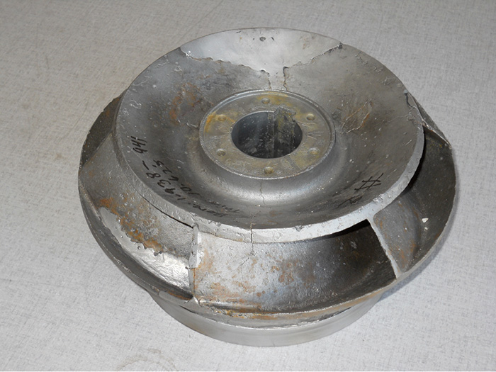 Figure 1. Original impeller
The images featured within this article represent the complete reverse engineering process. The model 12KK, vertical pump was disassembled. The components were lain out, and each component was analyzed to determine the repair process. This second-stage impeller (see Image 1) had wear and cracking (because of poor weld repairs made by another company). It was a perfect candidate for reverse engineering.
The impeller shroud and vane profiles were captured and diagnosed by an engineering team to identify design improvements.
Material upgrades were discussed, but the original material, 316 stainless steel, was considered acceptable for the service and application of this pump.
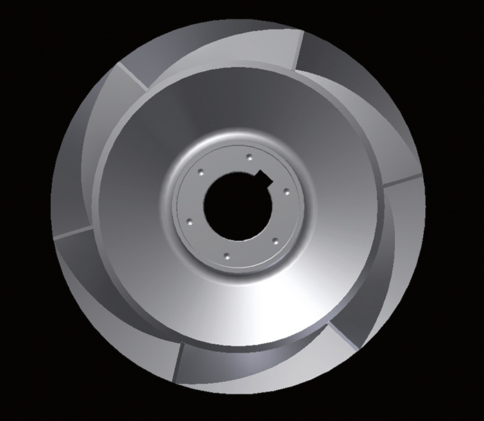 Figure 2. 3-D impeller representation
The direct replacement impeller (see Image 3) was made via rapid prototyping using the 3-D representation (see Image 2) and was produced in April 2011 for an electric power generation plant located in the southwestern U.S. It is currently operating with no issues.
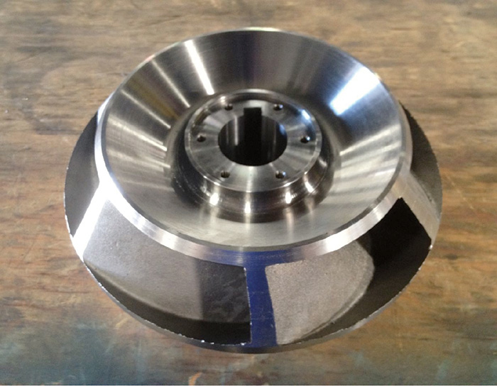 Figure 3. New replacement impeller