


A combined-cycle utility plant had eight feed pumps in the heat recovery steam generator (HRSG), and the horizontal multi-stage pumps were driven by 2,500-horsepower (hp) motors. Some pumps were running with high vibration levels. Over a few years, a dozen disc couplings failed. The cause of the coupling failures was not a mystery. In each train, pipe strain in the system was causing the pump shafts to move significantly as the fluid temperatures increased.
The thermal growth was different on each pump. Some had greater horizontal movement, and some moved more vertically. The pumps' movement was tracked over long periods of time and plotted using Permalign equipment. As an example, one pump had a maximum horizontal movement of 0.042 inches with a vertical maximum movement of 0.015 inches, although the movement was hardly predictable. At some points, the pump would grow in the positive vertical direction, and at other times, it moved lower than the starting position.
While correcting the pipe strain would be ideal, it was not feasible because of the time and expense. As a result, the plant operators looked at potential alternative solutions that would eliminate the downtime while minimizing the investment of time and capital.
The operators discussed a higher misalignment coupling. In the current layout, the distance between shaft ends was 8 inches. For a typical disc coupling with an angular misalignment capability of 0.25 or 0.3 degrees per disc pack, the total maximum allowable parallel offset would be between 0.030 and 0.035 inches. Considering the misalignment numbers previously stated, one can see why couplings were not lasting.
For a coupling to survive this amount of misalignment at the current distance between shaft ends, the angular misalignment capability per hinge would have to be at least 0.6 degrees. To allow for all other non-parallel and axial misalignment while still providing some extra margin for error, the angular misalignment capability per hinge would have to be closer to 0.7 or 0.8 degrees.
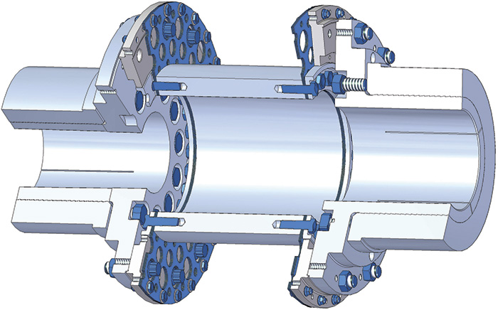 Figure 1. A typical flexible spacer coupling layout (Graphics courtesy of Coupling Corporation of America)
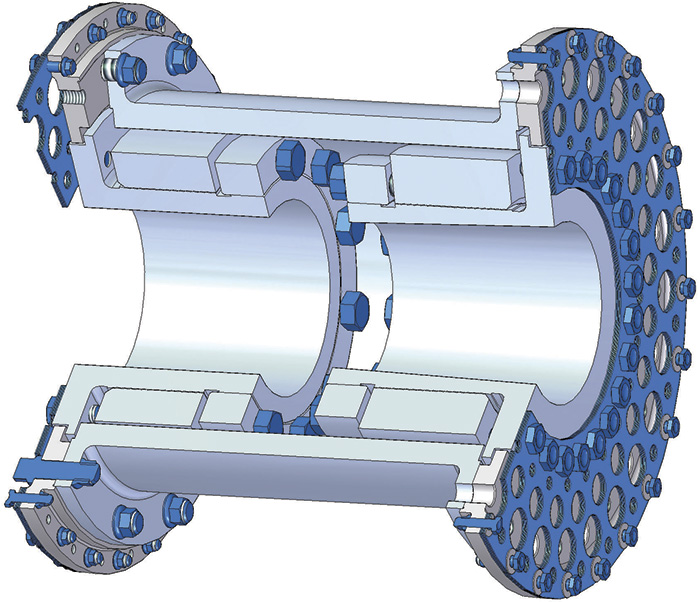 Figure 2. A typical close-coupled flexible coupling layout
Another strategy was to increase the distance between the hinge points of the coupling by a close-coupled design. Hinge points are defined as the imaginary plane about which a flexible element (disc pack or diaphragm pack) bends to accept an angular misalignment. Normally this style of coupling would be used when the shafts of the driving and driven machines are positioned very close together. Figure 1 shows a "spacer" coupling layout, while Figure 2 shows a typical close-coupled layout.
In many close-coupled designs, the flexible elements of the coupling are positioned on the back of the hub—closer to the machine housing and further away from the end of the shaft. This style can be synonymous with reduced-moment couplings as well. The result is an increase in the effective distance between hinge points of the coupling by approximately the combined length of the two shafts, whereas a normal spacer coupling layout has a distance between hinge points slightly shorter than the distance between shaft ends.
In this particular case, a close-coupled design seemed like a good fit because both shafts were more than 5 inches long, which, combined with the 8 inches between shaft ends, would give enough space to allow for a distance between hinge points of at least 18 inches. At that distance, a coupling with 0.3 degrees of angular misalignment capability would probably work, although 0.4 degrees would give a larger safety margin.
This strategy seemed like a good option until one other detail was discovered: an obstruction on the pump side that would not allow the larger diameter of the flexible element to be installed.
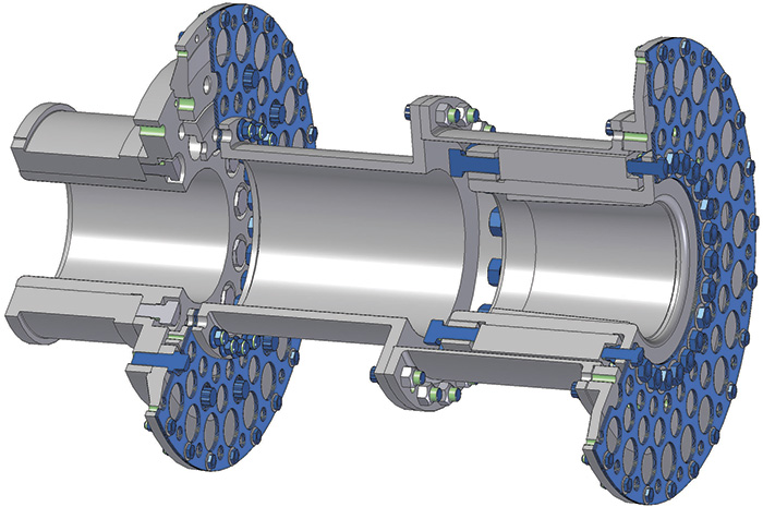 Figure 3. A combination of spacer and close-coupled coupling halves
Finally, a combination of a spacer and a close-coupled coupling could work. Because of the diameter restriction, a normal hub could be used, bolted to a spacer center section with a flexible element. On the motor side, without diameter restriction, a close-coupled style coupling could increase the distance between hinge points (see Figure 3).
With the dimensions of the shafts, this "hybrid" coupling layout could provide about 13 or 14 inches between the coupling's hinge points. With that much distance, a coupling with 0.3 degrees of misalignment could not provide enough extra misalignment margin to run safely. So a higher misalignment coupling would still be needed to meet the needs of the large thermal growth.
The final solution came in the form of a high-misalignment coupling with 0.5 degrees of misalignment per hinge. With that amount of flexibility, the coupling can handle about 0.115 inches of parallel offset, which is enough to have a large safety margin on the misalignment.
The plant decided to try one coupling using this style. It was installed on one of the more problematic units. After installation, the vibration issues on that unit were reduced to normal level. The only remaining question was how long the coupling could last running at those high misalignments. The first installation was about five years ago, and the coupling is still running successfully.
Since the original installation, the plant has upgraded the remaining units with the same new coupling, and the results have been similar.