


With the exception of hard-core pump enthusiasts, most pump users do not have much interest in or the need to get deep into pump design. What makes a five-blade impeller operate differently than a six-blade impeller? Why? How does a larger impeller eye affect the net positive suction head required (NPSHR)?
These are all fun questions, but they are of little practical value to a maintenance mechanic, plant reliability engineer or parts purchasing manager. However, by understanding pump hydraulics basics, users can learn some valuable information:
- How to improve reliability
- What features of the geometry of the impeller, casing and shaft mean
- What can spell trouble
Even a little scratching of the service of advanced pump methods can help save an operator money. This article will touch on what pump designers use in their quest for more efficient and reliable pumps.
Blade Shape
Impellers generally have backward-curved blades or forward-curved blades. The shape of the blades depends on the details of the hydraulic design. A centrifugal pump operates on a principle of imparting angular momentum to a fluid. The fluid must change direction as it passes through the impeller blade cascade.
Energy is also exchanged as mechanical torque is transmitted from the motor shaft to the hydraulic energy, which manifests itself in building pump pressure. Hydraulic designers refer to this as velocity triangles—one at the impeller blade inlet and another at the exit. A velocity triangle has peripheral velocity (U), absolute velocity (V) and relative velocity (W), with the impeller rotating clockwise (see Figure 1).
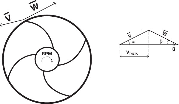 Figure 1. Backward-curved blades used in most pump impeller designs
Pressure Build and Outside Diameter
The ability to build pressure depends directly on the product U x Vtheta, which means that for higher pressure, the impeller outside diameter (OD) must be larger, or the pump should rotate faster. Either option makes the U vector longer. The relative velocity vector (W), including its magnitude and direction, must be such that the velocity triangle closes to produce the desired pressure and flow.
For most centrifugal pumps, this relative velocity vector ends up backward against the direction of U. The angle between vectors U and W is called a relative flow angle (beta), and the blade angle is set approximately equal to that. Beta (β) typically ranges from 10 to 35 degrees for most single-stage centrifugal pumps. However, at higher values of specific speed (Ns), such as with turbine pumps, it can be as high as 40 to 50 degrees.
Change of Blade Shape
Some machinery has significant space limitations, such as car hydraulic transmissions. In these situations, it is not possible to beef up U by the OD, and the only option is to curve the blades forward to create a large velocity Vtheta (see Figure 2) and build up the same pressure as in Figure 1.
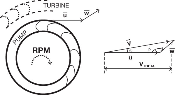 Figure 2. Special forward-leaning blades, such as in the pump of a hydraulic transmission
While this allows significant size reduction, the downside is low efficiency, because the absolute flow velocity becomes too large and would result in increased hydraulic losses for a normal pump. In a hydraulic transmission, however, there is a pressure recovery turbine, which sits immediately behind the pump. The turbine wheel blades are also curved to accommodate and match the exit velocity triangle of a pump. The turbine picks up and recovers the velocities produced by the pump.
As most pump impellers discharge directly into a volute or a diffuser without having a special recovery turbine wheel following the pump impeller, the majority of the designs have backward-leaning blades.
Computations
As you can see from the velocity triangles, head rises as flow is reduced. At zero flow, the meridional velocity vector is zero, and the tangential component of the absolute velocity is equal to the rotational velocity. This is the same regardless of the blade type or number. The equation for the ideal head becomes the following at zero flow (VTH = U):
H = (U x VTH)/g = (U x U)/g
For example, suppose a pump has a 6-inch impeller running at 3,600 rpm. The peripheral (tip) velocity of the impeller wheel is:
U = 6 x 3,600 / 229 = 94.3 ft/sec
H = 94.32 / 32.17 = 276 ft
(In Equation 1, the assumed inlet pre-rotation is 229—a conversion constant for U.S. units—and the gravitational constant is g = 32.116 ft/s2)
Note also that the width of the impeller does not factor into the equation, only the impeller OD. You may want to check a few pump curves in a pump catalog for the value of head at shutoff, as a matter of interest.
To learn more on these topics, come to PumpTec 2013: www.pumpconference.com.