


A refinery in Northwest Indiana is home to an internal power plant, which includes three high-pressure service water pumps. These pumps provide cooling water to the bearings for the forced-draft fans on top of the boiler house. They also cool two other pieces of equipment throughout the power plant. The pumps are 1947 vintage Ingersoll-Rand, 3BEV, two-stage horizontally split pumps (see Image 1). Packing is used for sealing instead of mechanical seals. In addition, the pumps use greased bearings and are designed to provide a flow of 500 gallons per minute (gpm) at 250 feet of total dynamic head (TDH). The pumps have been reliable with low vibrations. The main maintenance tasks are monitoring and replacing the packing and changing the bearings in the field.
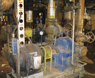 Image 1. The 3BEV, two-stage horizontally split pumps (Courtesy of BP Whiting Refinery)
After many years in service, the pumps began to degrade internally and stopped meeting the designed service requirements. Considering the critical nature of these pumps, the power plant unit determined that returning them to the designed performance levels was imperative. The unit's maintenance and engineering team developed a set of options and scheduled maintenance at the next available opportunity.
Considering the high cost of repairs (because of the pumps' size) and the fact that the existing pumps had a cast-iron body, opportunities for upgrades were scarce. Knowing that the pumps had not been repaired in more than 20 years, the team anticipated an extensive scope with significant costly internal and external weld repair (see Images 2 and 3). The team had a choice: They could either spend a significant amount of money on repairs to an obsolete pump or seek alternatives.
Since this work would be conducted under the routine maintenance budget, the scope had to be limited. It would not have the resources of a capital project, restricting what improvements could be made.
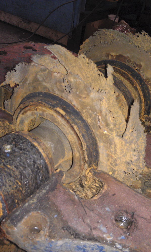
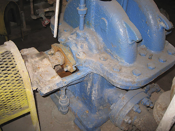 Image 2 and 3. The pumps had not been repaired in more than 20 years, so the team anticipated an extensive scope with significant internal and external weld repair. (Courtesy of BP Whiting Refinery)
Option One
The first option to consider was the purchase of a new pump. How much would a new, in-kind pump cost? The thinking was, if the price of a new pump were comparable to the repair, a business argument could be made for the purchase. Unfortunately, the cost of a new pump was more than twice the predicted cost of a repair.
Option Two
The second option was to reverse engineer the pump case at a third-party facility. However, the pump would still have the obsolete design with packing unless additional engineering was carried out. The additional engineering would add cost and lead time. The drawback of this option was the high cost of reverse engineering and the need to pull the pump for the duration of the project (reverse engineering, casting, manufacturing, assembly and testing). This choice was not ideal but seemed more feasible than the first option or the repair option.
Option Three
The third option considered was to evaluate several original equipment manufacturers' (OEM) product lines for a modern design pump that meets the hydraulic requirements and motor horsepower. Many were available in different designs that met these requirements and that provided metallurgy and design upgrades that were in line with the cost of the repair option. However, this change required foundation and piping modification which would add to the overall cost. This third option was considered acceptable in spite of its expanded scope and higher cost because of the advantages these upgrades provide.
Option Four
While these options were being considered, another project was in the works at one of the refinery's cooling towers, which became the fourth option for this project. This option was discovered by chance.
A fellow pump engineer was working with a company that reverse engineers impellers. For that specific application the refinery needed several impellers in a short period of time, and all the traditional avenues (OEM or reverse engineering) could not meet the deadline. Based on the positive experience of another engineer dealing with a similar challenge, he recommended contacting Sims Pump Company (Sims). This company reverse engineers impellers like other companies. However, it uses its own material, which is Simsite. The material is a graphite-combination-fiber, continuously interwoven, reinforced composite with phenolic/epoxy thermoset resin. The company was able to reverse engineer these impellers faster than any of the other options. The material offered its own advantages that included corrosion resistance and light weight.
During the discussions about the impellers, the unit's team wanted to learn more about the capabilities of reverse engineering and manufacturing pump casings using this material. The sales person provided the engineering team with information including the curve, outline drawing and service conditions for review.
During these discussions and with full understanding of this new approach, the unit team had to agree on a list of requirements, goals and potential drawbacks. Based on these discussions, the refinery's power plant team developed the following list:
- Meet the same hydraulic specifications.
- Maintain the same motor specifications (speed and power) to avoid motor replacement.
- Maintain the same footprint to avoid foundation work and changes.
- Maintain the same piping size.
- Maintain the same outline and flange-to-flange spacing and orientation to avoid piping alterations.
- The new pump should include mechanical seals instead of packing.
- Maintain the same coupling location to avoid motor relocation. This was not a major issue, but the team preferred this as part of the solution.
- The cost of the pump (engineering/manufacturing) must be comparable to the repair option, which was the lowest cost option of the other three under consideration.
Even though the list of requirements could not be achieved by the previous options without the drawbacks, the items became a requirement to be able to sell the idea of an unconventional pump. The reverse engineering company performed an in-depth analysis of the existing equipment and a compilation of the list of requirements. The engineering company responded that it was able to and would like the opportunity to complete this project according to the goals.
Upon agreement, the team sent the reverse engineers the pump curve, the first- and second-stage impellers from the warehouse and the information provided earlier. At the final stages of the project, the team was able to send the pump to verify the dimensions.
The reverse engineers analyzed the current pump design, an axial-split, two-stage, double-suction impeller pump. Knowing that centrifugal impellers with higher specific speed will have a higher hydraulic efficiency, the engineering company's team created a suction specific speed window to work within.
That was the first design change implemented, moving from a two-stage, double-suction impeller design (with a specific speed of 1,680) to a two-stage, single-suction impeller (with a specific speed of 2,376) to increase efficiency based on the net positive suction head available. Once the impeller design was finalized, Sims began the next stage of mechanical design and modeling (see Figure 1).
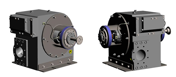 Figure 1. The 3-D model of the new pump prior to manufacturing (Courtesy of Sims Pump Company)
The end result was a new high-pressure service water pump (see Image 4) that offered:
- Near identical hydraulic capabilities
- The same motor specifications (rpm and speed)
- The same footprint with no change in the foundation or baseplate
- The same suction and discharge piping
- The same flange-to-flange spacing
- Mechanical seals
- No motor relocation requirement
- Comparable cost to repair option
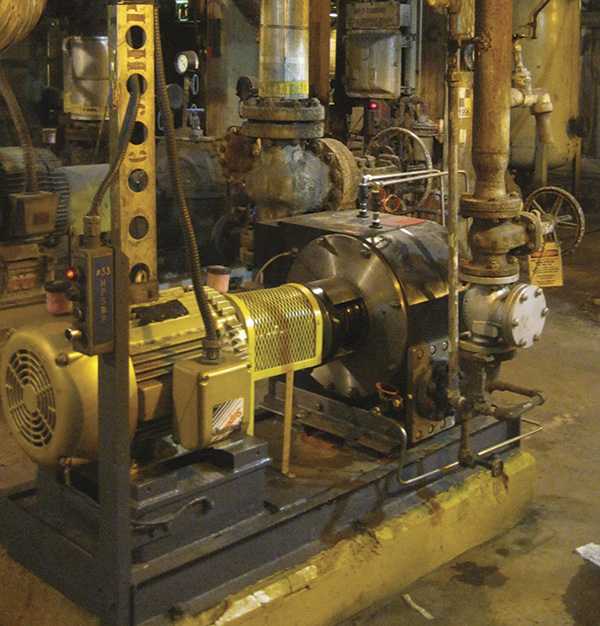 Image 4. The new high-pressure service water pump (Courtesy of BP Whiting Refinery)
In addition to the specified goals, the pump delivered some additional advantages because of the engineering work. These include:
- Pump case, impeller and bushings made from a material that does not corrode
- A bearing housing made of 304 stainless steel, which protects from corrosion if the seal leaks
- A 360 degree bearing housing designed for additional stability and ease of maintenance. The back covers can be removed to remove the bearings and the seals without pulling the bearing bracket.
- 410 stainless steel shaft for corrosion resistance
- More efficiency because of its single suction design
During the pump's installation, as with every scope, additions required further attention that would have been required regardless of the pump options considered. Because of the water damage from the leaking packing, the baseplate and pump foot pads were badly corroded and required repair and field machining. The motor foot pedestals were not level and also required repair. After these improvements, the pump was commissioned successfully with low vibration and bearing temperature. It delivered the performance that the refinery's power plant unit needed.