


Pumps with one, two or three pistons and crankshaft movement are the most common types of pumps. These are also the pump types that most need pulsation dampeners. Figure 1 shows the instantaneous flow during a complete crankshaft revolution for each type of piston pump. Each type of pump has the same piston dimension (diameter x stroke).
Figure 1 shows how a pulsation dampener works. The first curve represents a single-piston pump. The use of a dampener is important for this type of pump, otherwise no liquid flow is delivered during half of the revolution of the pump crankshaft. If the pump does not include a dampener, the diameter of the pipe must be calculated for the maximum instantaneous flow, which occurs in the middle of the piston stroke when the piston speed is also at its maximum. The flow curve is a sinusoid.
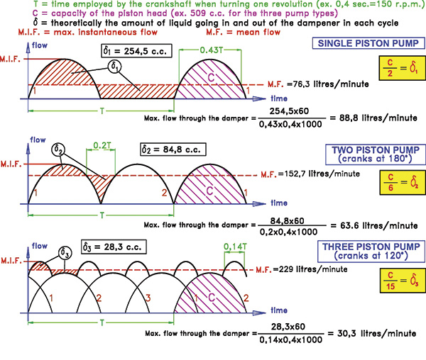 Figure 1. Pulsation dampeners store excess volume over the mean flow line of the total piston head during the piston impulse stroke. (Graphics courtesy of Hidracar, S.A.)
 From the point where a dampener is mounted, the maximum flow supplied to the circuit is close to the mean flow of the pump. This makes it possible to reduce the pipe diameter by approximately 40 percent, because the maximum instantaneous flow of the pump is 2.8 times more than its medium flow. In some cases, the reduction of the pipe diameter alone compensates for the cost of the dampener. The main advantage of a dampener is the stabilization of the circuit's pressure, which provides a variety of associated improvements. Pressure in a hydraulic circuit is basically a function of the flow. As the flow varies, the pressure varies.
The first curve in Figure 1 also demonstrates that the dampener stores excess volume over the mean flow line of the total piston head during the piston impulse stroke. The dampener then returns this volume (δ1)
back into the circuit during the piston suction stroke. In this type of pump, the volume stored by the dampener is half of the pump head or capacity per revolution.
Analyzing all three curves shows that as the number of pistons increases, the mean flow gets closer to the maximum flow, and the liquid volume δ1 stored by the dampener is correspondingly reduced. As a result, the required size of the dampener also decreases. This is easy to see when all the pistons in the three pumps have the same diameter, stroke and number of revolutions per minute.
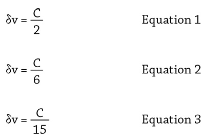
The more pistons a pump has, the lower the dampener size required and the smaller both the pipe section and the port connection between the dampener and the circuit can be, assuming the pumps provide the same flow independently of the number of cylinders. Equations 1, 2 and 3 show the relationship between δv and the capacity per head (C) for a one-, two- and three-piston pump, respectively. These are practical values for the calculation of dampener size.
When a gas is compressed, its pressure increases; when its volume expands, its pressure decreases. When a dampener is installed by the outlet of a piston pump, the pressure of the liquid in the circuit will fluctuate according to the volume of gas inside the dampener. This pressure variability, a +/- percentage of pressure, will be defined by the technical designer of the circuit or by final end user requirements.
The lower curve in Figure 2 shows the pressure fluctuation of a circuit with a dampener installed. This curve relates to the pump flow variation curve. A dampener stores the volume of liquid above the pump mean flow. For this reason, the minimum value of the pressure curve (P1 ) must coincide with the first crossing point of the instantaneous flow curve with the line of the mean flow. The maximum value of the pressure curve (P2) must coincide with the second crossing point, the moment when all δv has been introduced inside the dampener.
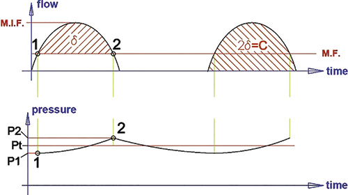 Figure 2. The flow and pressure fluctiuation of a circuit with a dampener installed
 The area between the instantaneous flow curve and the y-axis (time) represents a volume that, in the case of a single-piston pump, is equal to the pump capacity per stroke or revolution.
Flow x Time = Volume
In all hydraulic circuits, the pressure at the pump outlet port is a function of the flow, pipe length and diameter, viscosity of the pumped liquid, internal pipe surface roughness and geometric height. If the flow remains constant, the pressure needed to pump the liquid will also be constant as long as no change occurs in flow resistance. This type of change can be caused by sedimentation on filters, for example. This constant working pressure is known as Pt. When designing a circuit, the mean flow and the opposing resistances are needed to calculate Pt .
On one side, the dampener appears to stabilize the flow and pressure, but the pressure actually moves from P1 to P2. To stabilize the flow, the dampener needs to compress and expand a volume of gas. These pressure variations in +/- percentage of Pt regulate the values accepted in the circuit.
This pressure fluctuation can be reduced to very small values by increasing the volume of the dampener. P1 and P2 are the percentage values of Pt, which are pressure variations that the end user must determine. Manufacturers recommend that these variations are at least +/- 2 percent, because the environmental temperature conditions will likely modify the theoretical calculation.
Mounting Suggestions for Maximum Dampener Efficiency
The single-piston pump has the highest maximum instantaneous flow/mean flow ratio and the highest value for δv, which is the liquid entering and exiting the dampener each cycle. The following examples and recommendations will focus on single-piston pumps.
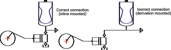 Figure 3. Proper mounting of a pulsation dampener
Figure 3 shows the proper mounting of a pulsation dampener. The following recommendations should be observed:
- The dampener must be mounted with its axis aligned with the axis of the pump outlet.
- The distance between the pump outlet port and the dampener port connection must be as short as possible.
- The pipe section between the pump and the dampener connection must be calculated for the pump maximum instantaneous flow.
- The remaining pipe section of the circuit must be calculated for the mean flow.
Figure 4 illustrates many of the principles discussed in this article.
ω: Pipe section for the mean flow
Ω: Small length of pipe section for the maximum instantaneous flow
Q: Maximum instantaneous flow
q: Mean flow
L: Distance between pump and dampener, as short as possible
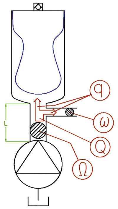 Figure 4. A visual of the recommended system
Fluid mechanics principles can show the difference between in-line and derivation mounting to a circuit and the higher efficiency of in-line mounting. The flow of a liquid inside a pipe follows different speed lines. The velocity is higher in the center of the pump, while it is nearly zero close to the pipe inner wall (see Figure 5). If the mean liquid velocity increases, the difference between the dynamic pressure (measured in the liquid movement direction) and the static pressure (measured perpendicular to the liquid movement direction) also increases.
Figure 5 reflects this concept. In-line mounting corresponds to the dynamic pressure reading. Derivation mounting corresponds to the static pressure. This assumes that the fluid circulates in a laminar regime.
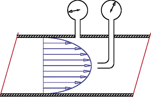 Figure 5. The velocity is higher in the center of the pump but nearly zero near the pipe's inner wall.
If the dampener is mounted in derivation and far from the pump outlet, its efficiency will be significantly reduced. If it is also installed in a pipe section with a smaller diameter than the main circuit pipe, the effect of the dampener will be negligible.
The pulsation dampener admission duct must be wider than its connection port. Any reduction in the diameter when attached to low pressure circuits will greatly reduce the performance and efficiency of the dampener.