


Variable frequency drives (VFDs) have been widely applied to pumping applications for nearly 30 years to provide variable flow and pressure output to meet changing conditions in commercial buildings. While the affinity laws for centrifugal loads explain the large energy savings potential due to speed reduction, the individual components of this "variable speed system" have not historically been examined or held to any efficiency standard. VFDs are also commonly packaged with options for pump applications like harmonic filters, EMC filters, dV/dt motor filters and contactor bypass, which impact system efficiency. Even VFD parameters adjusted during startup can affect how much power is consumed by both the VFD and the motor.
To establish some means of evaluating these systems for efficiency, the Air-Conditioning, Heating, and Refrigeration Institute (AHRI) formed a VFD task force in 2006 to develop a performance standard for VFDs. The result was the publication of
AHRI Standard 1210 (IP) and 1211 (SI) Performance Rating of Variable Frequency Drives.
The complete standard sets a minimum of three test criteria for VFD manufacturers to publish under the newly published guidelines:
- Drive System Efficiency (percent)
- Motor Insulation Stress, Peak V and Rise Time (µsec)
- Power Line Harmonics, Total Harmonic Current Distortion (THDi) (percent)
This article will focus in detail on the Drive System Efficiency aspect of the standard.
Calculating VFD Efficiency
If system efficiency is to be determined for a VFD, one might think it can be as simple as measuring the power into and out of it, then dividing the two measurements to represent it as a percentage value. The AHRI VFD task force quickly realized it was not that simple.
Even small changes to the drive setting, such as carrier switching frequency, could have a large impact on VFD efficiency. Likewise, in order to provide a standard method of test, basics like connected motor style, cable characteristics between the drive, and the motor had to be standardized. Electrically, power source impedance, phase imbalance and power factor needed definition in order to establish a standardized system where a user would be able to compare data between compliant drives and be assured that it was collected and published based on the same system.
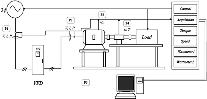 Figure 1. AHRI standard test setup for drive system efficiency and power line harmonics
(Graphics courtesy of Schneider Electric)
P1 - Closest point less than 1 m to input terminals of the VFD
P2 - Closest point less than 1 m to input terminals of the motor
P3 - Temperature sensor installed on the motor stator winding out of the cooling air circulation path
P4 - Torque/speed sensor between the motor and the load
P5 - Ambient temperature sensor near the cooling air entering the motor
Figure 1 shows the standardized test setup defined in AHRI 1210 and 1211.
Drive Technology
Today's VFDs have three power component sections: an input rectifier, a fixed DC-bus section and a transistorized inverter. Each design can differ slightly in components, as well as how the power devices are controlled—all of which have an impact on their efficiency. In the early 1990s most VFDs were updated to include newer power semiconductors, and insulated-gate bipolar junction transistors (IGBT) were controlled by pulse-width modulation (PWM) algorithms. This change greatly enhanced reliability and reduced the overall size of VFDs, allowing electrical variable speed control to replace mechanical methods of varying flow in pump systems.
 Table 1. Typical efficiency values as shown in VFD product literature
Even though the majority of pumping systems rarely require running at full load and speed, the efficiency calculations and subsequently stated values for VFDs are typically represented as a single percentage value. Table 1 shows typical efficiency values in VFD product literature.
Consulting engineers took this information and placed minimum efficiency requirement values in specifications as seen in the example below.
A. The alternating current (AC) drive shall be designed to operate at the input line voltage indicated on the equipment schedule.
B. The AC drive shall operate from an input frequency
range of 60 Hertz (Hz) ±5 percent.
C. The displacement power factor shall not be less than 0.96 lagging under any speed or load condition.
D. The efficiency of the AC drive power converter at 100 percent speed and load shall not be less than 97 percent.
E. The AC drive shall be sized to operate a variable torque load, and rated overcurrent capacity shall be not less than 110 percent for one minute.
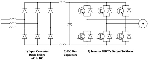 Figure 2. Typical VFD circuit diagram
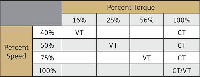 Table 2. Speed/torque test points for drive system efficiency. Please note: Output frequency or other readouts from the VFD shall not be used to determine percent speed. Only those cells that contain CT or VT are test points.
VFD Efficiency
While a single value did provide some comparison of VFD efficiency between manufacturers, it did not provide a means of comparison at any point other than full load and speed, where equipment rarely operates in modern variable volume systems. AHRI Standard 1210 and 1211 addresses this issue by requiring test data be published at four speed and torque points representing a variable torque fan or pump motor load, or a constant torque positive displacement pump or compressor loads. Table 2, taken from the AHRI Standard, illustrates data that must be published by manufacturers seeking to be certified.
Certified VFDs
With the release of AHRI Standard 1210 and 1211, specifying design engineers, owners and energy managers can compare VFDs on an equal basis. Efficiency has been the driving force behind motor regulations that define minimum levels of acceptable power usage.
VFDs now have a similar tool for those trying to maximize system efficiency with detailed operating points that closely define where fans and pumps operate within variable volume systems. As a result, simple, certified test data will be published following third-party verification testing to comply with these new standards.
Trusted Certification Program
AHRI Certified products are verified to perform as specified by the manufacturer, and the process of certification holds them accountable for their reported efficiency ratings.
This globally recognized, industry-respected approach to product certification carries benefits for consumers and specifying engineers.
The performance of equipment in the program is independently measured and verified, allowing for fair product comparisons. Equipment must undergo rigorous testing by independent, third-party laboratories under contract to AHRI.
References
ANSI/AHRI Standard 1210 (I-P) and ANSI/AHRI Standard 1211 (SI)