


What Are Your Vibration Monitoring Goals?
Identifying goals before starting is key to designing a process tailored to specific needs. What are you hoping to accomplish by monitoring vibration? How would you like to acquire data? What are you going to do with the data? These important questions should be addressed before moving forward.
Users typically take two different paths when it comes to acquiring data: Fast-Fourier Transform (FFT) and overall vibration.
An FFT plot shows the vibration spectrum as a function of frequency. These plots are typically acquired via a portable industrial data collector or online vibration monitoring system. Similar to sound and noise measurement, an FFT plot allows the user to diagnose the source of vibration and begin the troubleshooting process.
Overall vibration is more simplistic and typically measured with PLC, DCS or SCADA systems that already exist in the plant. Simple displays can also be used. The overall vibration is similar to a running average and is plotted against time for trending purposes. This measurement indicates if vibration has increased over time. Trouble lurks as vibration levels increase. An overall vibration signal can help save on downtime by allowing the user to predict impending failures and schedule maintenance on plant machinery.
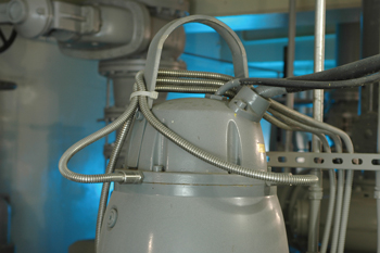 |
| A vibration sensor on a pump in a water application. |
Industrial Accelerometers-The Key Specs
Analog industrial accelerometers are used with portable data collectors or even 24/7 online monitoring systems. They are capable of providing both FFT and vibration trending data.
Sensitivity
Sensitivity is one of the most important factors when selecting an industrial accelerometer. The "industry standard" is 100 mV/g. This sensitivity will cover most applications, and data collectors are commonly supplied with 100 mV/g accelerometers and pre-configured with 100 mV/g as their default input sensitivity.
Slow speed rotating machinery running at less than 60 cpm may require a more sensitive accelerometer. Models marketed for "low frequency" applications are typically 500 mV/g. An increase in sensitivity creates a trade off as measurement range is reduced. Vibration levels in slow speed machinery are low. However, the increased sensitivity and resolution are an acceptable trade-off versus measurement range.
High speed machinery running at more than 60,000 cpm or impacting applications often use a 10 mV/g accelerometer.
Fit, Form and Function
Of course, any accelerometer needs to be able to fit into and survive the application. A common theme with industrial accelerometers for most every manufacturer is case isolation, hermetic sealing and the use of stainless steel housings. Industrial accelerometers are meant to survive in paper mills, refineries, steel mills, water-treatment plants, etc., but there are some nuances to consider.
Accelerometers with an integral cable are typically submersible. Be sure to pay special attention to the cable jacket's material. For example, polyurethane cable can degrade in a caustic application.
The industry standard for sensors with separate cables and connectors is to use a 2-pin MIL style connector. This rugged connector is threaded with an internal keyway and hermetically sealed onto the accelerometer. When paired with the right cable connector, these sensors work well in outdoor applications where they will be subjected to the elements.
Low-profile accelerometers with integral cable, also known as side-exit models, are popular for downhole pump applications. These models allow for limited clearance and submergibility.
Temperature Requirements
The common IEPE industrial accelerometer has a high temperature limit of 250 deg F. A quartz or ceramic sensing element is inside the accelerometer. This element, when subjected to vibration, outputs a unit of charge referred to as a pico-coulomb. This charge is then converted to a measureable voltage signal by the sensor's internal amplifier. This amplifier will fail when subjected to higher temperatures. High temperature IEPE accelerometers are commonly available that use a military grade amplifier to extend the sensor's temperature range to ~325 deg F.
For applications above ~325 deg F, an accelerometer design where the voltage amplifier is contained inside a separate housing and installed in a cooler area must be used. Charge mode accelerometers are industrial accelerometers without an internal amplifier. Typically sold in kits that include a high temp Teflon cable and a separate charge amplifier, these sensors are available to suit applications up to ~900 deg F.
Quartz versus Ceramic Sensing Elements
Ninety percent of the industrial accelerometers on the market today use a ceramic element, which allows for a superior signal to noise ratio versus quartz. Signal resolution is better with a ceramic element.
Quartz, however, is naturally piezoelectric and more stable versus ceramic over time. Quartz experiences less thermal shift in sensitivity and is recommended for applications where temperatures fluctuate.
Overall Vibration Sensors (4-20 mA)
Most plants have PLC, DCS or SCADA systems already in place that interface with sensors that monitor temperature, pressure, etc. Using the acquisition system already in place is a great way to start monitoring and trending vibration.
Overall, loop-powered vibration sensors (vibration transmitters) output a 4-20 mA signal and interface directly with existing PLCs without the need for costly signal conditioners, power supplies or monitors. These sensors use a ceramic sensing element, an internal amplifier and an RMS to DC signal converter.
Many of the same specifications and properties that apply to industrial accelerometers apply to vibration transmitters as well. These sensors are hermetically sealed, case isolated, contain internal RF and EMI protection and are made of stainless steel. They are submersible when supplied with an integral cable but are more commonly supplied with a 2-pin MIL connector.
The most important aspect to selecting an overall vibration transmitter is full scale range. Models scaled in inches per second are most popular. It helps to have some baseline idea of typical vibration levels as resolution is sacrificed for full scale range.
Is Hazardous Area Approval Required?
Is the machine to be monitored located inside a hazardous area where gas or potentially explosive fine dust is present? In this case, a certified non-arcing or sparking sensor is required.
The nuances of the various governing agencies, approvals, groups and divisions are too numerous to mention in this article. Most sensor manufacturers offer certified industrial accelerometers, vibration transmitters and switches. Most data collector manufacturers also have certified acquisition systems.
The nature of the hazardous area will determine whether or not an energy limiting barrier is required between power supply and sensor. Cases where the potential for hazard is constant typically require a barrier. Sometimes hazardous material is only present under an abnormal condition, and in this case a barrier is not required if the power supply is approved through the proper governing body.
Be sure to thoroughly understand hazardous area requirements before installing any vibration sensing device.
Tips and Tricks
Mounting
Vibration sensors can be mounted via their supplied mounting stud, adhesive mounting base or magnet. Since adding weight to the measurement system causes the high frequency range of the accelerometer to decrease, the best mounting method is via the supplied stud.
Temperature Output
Both analog industrial accelerometers and overall vibration sensors can be supplied with an optional, additional temperature output allowing the user to obtain vibration and temperature readings from the same sensor.
Troubleshooting
Industrial accelerometers have a DC component to their output signal referred to as the bias voltage. Typically only the AC component of the signal is of value because it represents machine vibration. However, the DC bias voltage can be measured to discover if the sensor is dead or the cable has electrically shorted out. Most portable data collectors have a function that allows the user to measure the bias voltage.
Portable handheld calibrators are a popular marketplace tool. These devices allow the user to perform a quick calibration check of the accelerometer to ensure the industrial accelerometer's sensitivity is still within specification. The calibrator vibrates at a fixed level and frequency with the sensor mounted on top.
 |
| An integral armor cable accelerometer in oil. |
Cabling
The weakest link in any industrial measurement chain is cable. In the field, cables get pulled, stepped on, climbed on, cut, burned, frayed, zapped, melted and fried. Cables are typically two-conductor, twisted, shielded pair.
The cable's jacket is the most critical aspect in cable selection. Polyurethane cables are the easiest to work with as they have the tightest bend radius and are the most flexible. They are submersible and excellent for outdoor use. Teflon cables are recommended for high temp or caustic applications. Armor jacketed cables are commonly used in cutting-tool applications or any scenario where the cable can easily be cut or damaged.
Long Cable Runs
Analog IEPE industrial accelerometers and 4-20 mA loop powered vibration sensors are well suited for industrial applications because electrical interference does not easily affect them. A loop powered sensor's 4-20 mA signal can run hundreds of feet to the control room without degradation. IEPE sensors will experience high frequency signal attenuation when traveling more than 100 ft. Often the attenuation does not affect the frequency of interest. However, power supply current can be boosted to drive the signal greater distances.
Cable interface boxes and multi-pair cables can save time, space and money. An interface box accepts inputs from multiple sensors via a terminal strip. A multi-pair cable can then be connected to the terminal strip, allowing multiple channels to travel to the acquisition point on one cable.
 |
| A handheld calibrator, plus a data collector and sensor. |
 |
| A sensor with separate cable and connector mounted on a machine. |