


The biggest decision is determining which tolerances to align.
In the alignment training classes that we teach, questions arise about alignment tolerances. We often ask, “What are your company’s alignment tolerances?” Here are the most common responses:
- We don’t have any.
- Zero.
- As close as we can get it.
- When we get a smiley face!
- When the coupling turns green.
- Whatever the equipment manufacturer tells us to do.
The purpose of this article is to shed some light on the topic of alignment tolerances.
Which “Alignment” Are We Talking About?
The alignment in this article is typically referred to as coupling alignment. In reality, coupling alignment is not about aligning couplings at all. It is about aligning shaft centerlines. The shaft centerline of a moveable machine—typically a motor—is aligned to the shaft centerline of a machine that generally is not moved, such as a pump.
What Is Shaft Centerline Alignment?
Shaft centerline alignment is the positioning of the rotational centers of two or more shafts such that they are co-linear when the machines operate under normal conditions. There are two types of misalignment, offset and angular (see Figure 2).
When shafts are aligned, the offset and the angular must be aligned. The alignment must be on two planes—vertical and horizontal.
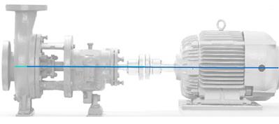 |
| Figure 1. Shaft Centerline Alignment |
 |
 |
| With an offset misalignment, the shafts of the two machines being aligned may be parallel, but not in the same plane. When properly aligned, the shafts are co-linear, which means that any point on either shaft lies in a straight line with any other point on either shaft. | With angular misalignment, the two shaft centerlines being aligned intersect, or form an angle relative to each other. The coupling faces will be at the same angle of misalignment as the shafts, unless they are bored incorrectly. |
| Figure 2. Two types of misalignment |
Why Align?
The goal is to align shaft centerlines. The main reasons for aligning shaft centerlines are:
- Increased reliability of the equipment being aligned
- Decreased wear on the bearings, seals, gears, couplings and other components that make up the machines being aligned
- Reduced vibration levels
- Decreased energy consumption (typically a small amount, but sufficient misalignment can cause increased energy consumption)
- For warranty purposes, because machine manufacturers specify it
Alignment Tolerances
The definitions of alignment and misalignment and why we align are straightforward. However, tolerances are like opinions—everybody has them.
All laser manufacturers and coupling manufacturers have determined their alignment tolerances. Most alignment training organizations and engineering firms have them, as well. They are all different.
AGMA has very specific tolerances on gearing. AFBMA has specific tolerances on bearing sizes. NEMA has specific designations for motors. ASTM, ISO, API—pick an acronym, they all have specifications on machinery. Why isn’t there a governing body for alignment?
Simply stated, no industry standard on alignment exists because too many variables are involved. Some of these variables are:
- Couplings—Couplings are made by numerous manufacturers. Some are completely rigid, and must be aligned to near zero misalignment. Many modern couplings are flexible. Of those, many use a sliding motion—such as a lubricated steel grid—to tolerate misalignment. Some use rubber; neoprene; nylon bushings; or thin, laminated steel discs, because these have the ability to flex for millions of cycles before failing. Some use a combination of both sliding and bending action. Some may tolerate a great amount of angular misalignment but little offset. Some tolerate substantial offset, but cannot handle any angular misalignment. Modern coupling designs all tolerate a certain amount of misalignment based on their design, but their limits can all be exceeded, if enough misalignment is present.
- Material stiffness, hardness, toughness, diameter, length and geometry—There are as many configurations of shafting metallurgy as there are of couplings. Whether it is called cold rolled; tool steel; stainless, or turned, ground and polished—shafting is designed to tolerate a number of factors. However, machining can change its stiffness, bending moment and torque handling capabilities. Components are mounted to it, such as impellers and fans. Then it is supported by bearings, and fluid is held in place by seals or packing. Why does that matter? Because the ability of all these materials to bend or deflect is based not only on size, geometry and metallurgy, but also on static and dynamic radial and axial loads. Bearings and seals can fail prematurely if they are exposed to excessive radial or axial loads, some of which can be caused by misalignment.
 |
 |
| Figure 3. Using a rubber band to demonstrate the forces generated by a flexible coupling element |
- Load and Torque —The same type pump might move water or gypsum slurry, but the fluids have different specific gravities and start-up torque loads. Even the same pump, pumping the same liquid, would have a different torque load based on pushing against a 2-foot column of water, as opposed to a 20-foot column of water.Speed—This does not affect a machine’s ability to tolerate misalignment. It is the number of cycles of bending before fatigue occurs. A misaligned shaft turning at 3,600 rpm will bend twice as many times per minute as the same shaft turning at 1,800 rpm. The couplings themselves are also designed not to exceed certain speeds.
Given the variables, understanding why no universal industry standard on alignment exists is easy. However, many companies offer alignment tolerances.
Coupling Manufacturers
Some mechanics measure alignment quality using the coupling manufacturer’s recommendations. Most coupling manufacturers’ alignment tolerances are based on the amount of misalignment the coupling will tolerate before failing. The coupling may tolerate a great deal of misalignment, but the bearings, seals, shafts, gears, etc., may not.
Think of a simple, wide rubber band (see Figure 3). If it is stretched between the fingers until just straightened out, it takes little force to keep it in that position. But if it is stretched until just before the point of breaking, it requires a great deal of force to hold it in place. It is still a rubber band, just doing its job. However, the knuckles and fingers of the person pulling the rubber band apart are working much harder.
While the coupling manufacturer may design a good coupling that tolerates a large degree of misalignment, the other machine components may not tolerate that much misalignment. Because of this, basing alignment quality on the coupling manufacturer’s misalignment tolerance is not a good idea.
Design Engineers
A design engineer considers many of the variables when making a determination about a machine’s design. A typical pump is used as an example.
- Pump—The engineer would size the pump based on how much liquid would need to be moved per minute, the pressure required, etc. Normally, this information comes from the pump manufacturer, who has specified its pumps based on design and testing.
- Motor—The engineer would size the motor based on the amount of horsepower required to do the work that the pump is called to do. Again, this information would be drawn from the motor manufacturer, who has done extensive testing to determine motor performance.
- Coupling—The coupling manufacturers have also done extensive testing on their couplings to determine the best geometry and materials to allow the coupling to transmit power. Many times, the coupling is also designed to be the weakest link. In other words, the coupling is designed to fail if horsepower, torque or load limits are exceeded. The coupling should fail before the shafts do.
The engineer draws upon all this information (and more, such as piping, controls, etc.) to determine the machine’s design.
However, who determined the alignment quality?
- The coupling manufacturers’ tolerances—This could be a mistake. Many coupling manufacturers’ alignment tolerance are based on how much the coupling will tolerate not how much other equipment will tolerate.
- The motor or pump manufacturers’ tolerances—These tend to be tighter than the coupling manufacturers’, but where do they get their numbers?
- Engineering studies—A few of these are available. Notably, the University of Tennessee and the U.S. Navy have conducted studies on how alignment affects energy consumption (very little) and bearing failure (much more substantial). Computational Systems, Inc., (CSI) has also published good materials on how misalignment affects vibration levels on machinery.
- Technical publications—Good reference materials have been published on machinery alignment. John Piotrowski’s “Shaft Alignment Handbook” and “Audel’s Millwright’s and Mechanic’s Guide” are both great references. Victor Wowk, and others, have also published useful books.
- Laser alignment tool manufacturers—They have alignment tolerance recommendations, as well. While they may all tout the benefits of their particular machine’s ease of achieving the specified alignment quality, all their alignment tolerances are close to one another.
- Machinery owners—Many large corporations have adopted alignment quality guidelines. Some of the guidelines are based on the same sources listed above. A few might have participated in engineering studies to determine what works best for them. Some may have just been written by some guy who was tasked with developing an alignment tolerance for the company he worked for, and he borrowed it from someone else.
Tolerance Comparisons
All this shows that a lot of material is available on what alignment tolerances are, what alignment quality should be and how alignment affects bearing life, seal life, vibration levels and coupling wear.
Figure 4 shows a comparison of alignment tolerances on a 1,785 rpm pump, using the alignment tolerance recommendations from four pump manufacturers and three laser alignment tool manufacturers.
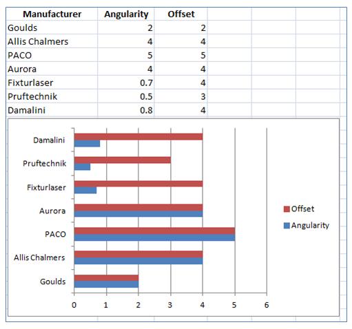 |
| Figure 4. Alignment tolerances for different pump and alignment companies |
So far, this article discussed the opinions and research of many intelligent people who work for reputable companies, who spent great amounts of time, money and resources to specify alignment tolerances. No disrespect intended, but most of these intelligent, well-meaning people are not out installing, aligning and maintaining machinery every day. That is left to the mechanics, millwrights and maintenance technicians—the ones who pull the wrenches. They are the final arbiters of alignment quality.
Whose alignment specification do we use? Taking the tightest angular alignment value listed in Figure 4 (Pruftechnik’s 0.5 mils per inch) and the tightest offset (Goulds’ 2 mils), can an end user align to this? Absolutely.
We conduct alignment training throughout the U.S. The students in our classes routinely align to 0.3 mils per inch angularity and 1 mil offset, whether they are using alignment demonstrators or working on real machines.
Whose alignment tolerances should end users follow?
- The coupling manufacturer? All day long.
- The equipment manufacturer? Easy.
- The laser tool manufacturer? Can do.
- You company’s alignment specs? Sure.
- Yours? Yours should be at least as precise as any of those mentioned.
Alignment quality is ultimately based on two things—the expertise and desire of the maintenance person to perform quality work and the ability of the alignment tool to measure to the accuracy desired.
If these two factors are used, alignment can be performed to within any realistically-specified tolerance.
References:
- Zdrojewski, D. VibrAlign. “Precision Shaft Alignment is Possible.” Reliable Plant, 9/2007.
- Hines, J.W., Jesse, S., The University of Tennessee Maintenance and Reliability Center Motor Shaft Misalignment Research Project (Paper #982083), Society of Automotive Engineers, copyright 1997.
- U.S. Department of the Navy.
- “Laser Alignment,” CSI Training Manual, Computational Systems, Inc., 1998.
- Piotrowski, J., Shaft Alignment Handbook, 3rd Edition, 2007.
- Davis, T. B., Nelson, C., Audel’s Millwrights and Mechanics Guide, 5th Edition, 2004.
- Wowk, V., Machinery Vibration: Alignment, 2000.
- Goulds Pump Industrial Products, Field Alignment.
- A-C Pump division of ITT Industries.
- Paco Pumps, Grundfos CBS Inc.
- Aurora Pump.
- VibrAlign.
- Pruftechnik.
- Damalini.