


Vibration levels at the top of a vertical motor in a typical pump-motor structure (see Figure 1) remain an area of interest in the pump industry. This article provides a mathematical model for estimating the vibration at the top of the motor to compare to empirical data and provide insight into how parameters can impact the vibration level produced. This insight may help those in the industry understand vertical pump vibration and assist in the development of standard vibration acceptance criteria.
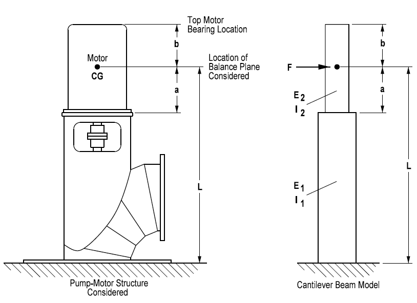
Figure 1. Typical vertical pump-motor structure
Current vibration standards provide acceptance criteria for measurement locations at the top of the motor support (near the bottom of the motor) for vertical pumps. Guidance on acceptance levels for the top of the motor is not provided. General consensus among standards-producing organizations is that measurements obtained near the motor bottom are best suited for pump acceptance.
Provided the structure is not in resonance, this is a fair approach. For a fixed vibration acceptance criterion near the bottom of a motor, the vibration response at the top of the motor results from the motor properties that can vary considerably. Figures 2 and 3 show a sample of observed motor reed frequencies and the derived stiffness using data from different manufacturers’ motors. Motors with such varying properties may be expected to produce diverse vibration responses at the top of the motor for the same level of vibration near the bottom of the motor.
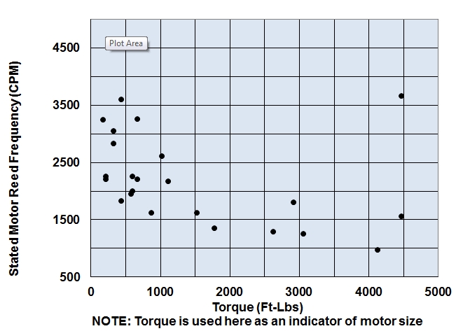
Figure 2. Observed typical values of stated motor reed frequency versus torque
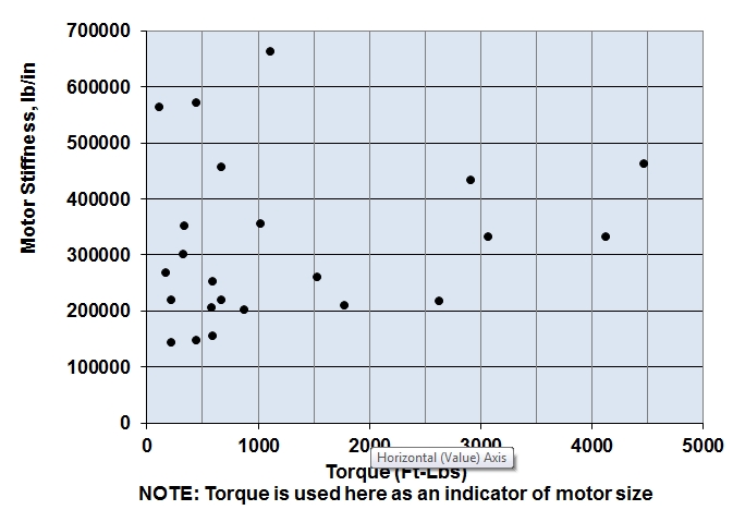
Figure 3. Observed typical values of motor stiffness versus torque based on stated motor reed frequency values
The pump head that supports a motor can also vary. Structure heights and weights are different, as are the mechanical design and material properties. Consider that the modulus of elasticity that relates to deflection (and vibration) for cast iron is about half that of steel, but conversely, the damping capacity of gray cast iron is considerably greater than that of steel. To top it off, bearing manufacturers’ research studies regarding the impact of vibration levels on bearing life are lacking. Such information would help the industry weigh the costs of lower vibration levels versus the benefits. This comparison is important because providing low vibration levels in a vertical pump-motor structure may significantly impact the equipment’s initial costs, and higher vibration levels can impact long-term maintenance costs.
These issues represent a few challenges faced when considering vibration acceptance criteria at the top of the motor. A mathematical model may help provide insight and is examined in this article.
This material is presented with the following simplifying assumptions because the pump-motor structure’s vibration can be complex:
- The primary focus is the vibration at the operating speed due to residual imbalance of a motor used on a vertically suspended pump.
- The structure of interest is the area above the baseplate.
- Of necessity, the natural frequency of the vertical structure must be discussed. This discussion is limited to the reed frequency—the first bending mode lateral natural frequency above the baseplate.
- In a particular structure, other relevant modes of vibration, corresponding natural frequencies and other relevant excitation sources may be experienced, but these are not included within the scope of this article.
Modeling the Motor Properties
Examining the reed frequency of the vertical pump-motor structure begins with knowing the reed frequency of the motor. National Electrical Manufacturers Association (NEMA) MG 1 references the motor properties that are typically supplied by the motor manufacturer:
- The reed frequency
- Motor weight
- Distance to the motor center of gravity from the motor mounting flange face
- The static deflection of the motor center of gravity (CG)
The motor static deflection is the deflection of the CG when considered mounted to a rigid foundation, turned horizontally and deflecting under its own weight. As stated by NEMA, the motor reed frequency (fn)—in cycles per minute (CPM)—and the motor static deflection (Δs, in inches) are related as shown in Equation 1.
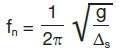 Equation 1
Where g = 1,389,600 in./min.2
The effective motor frame stiffness is obtained from the classic spring stiffness equation (see Equation 2).
 Equation 2
Where:
k = The effective stiffness of the motor frame
W = Weight of the motor (pounds)
Equation 2 was used to determine the values of k shown in Figure 3. Note that the deflection of the motor CG location may also be represented by a simple cantilever beam model as (see Equation 3).
![]() Equation 3
Equation 3
y = Δs (in.)
F = The motor weight (pounds)
a = The distance from the mounting flange to the CG location (in.)
E = The modulus of elasticity of the motor frame material (psi)
I = The effective moment of inertia of the motor frame (in.4)
Modeling the Structure Properties
The stiffness of the structure resists the residual motor imbalance force. Therefore, it is the structure properties that are of interest and not just those of the motor, in particular the reed frequency of the structure (fn). When considering the structure reed frequency, it is important to understand that, by placing the motor on a support structure (a pump head in this case), the CG of the motor is higher. This additional height and flexibility introduced by the support will cause the motor CG to have a higher value of static deflection. This results in a structure reed frequency that is lower than the motor reed frequency alone.
Using a lumped-mass model approach and ignoring the mass of the motor support, the vertical structure may be modeled as a stepped cantilever beam (see Figure 1), with the beam’s upper portion representing the motor and the lower portion representing the pump head. For this model, the deflection at the motor CG location (located a distance L from the foundation), because of a force, is represented by Equation 4.
 Equation 4
It should be noted that the deflection above the motor CG—along dimension b up to the motor thrust bearing measurement point—is linear (no bending) and depends on the slope of the deflection curve at the motor CG. Therefore, the deflection at the top of the structure due to a force (F) at the motor CG location is equal to Equation 5.
![]() Equation 5
Equation 5
 Equation 6
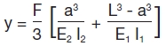
Equations 5 and 6 will come into play later in the article. For now, substituting Equation 3 into Equation 4, using motor weight (W) substituted for F, yields the structure static deflection (Δs) as shown in Equation 7.
![]() Equation 7
Equation 7
Now, using Equation 7 for the structure static deflection, substituted into Equation 1, the structure reed frequency is shown in Equation 8.
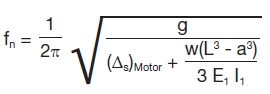 Equation 8
Modeling the Vibration Response at the Motor CG
Knowing the reed frequency of the structure, the classic solution for rotating imbalance may be applied. This is described by William Thomson, Theory of Vibration With Applications, 4th Edition, page 96, with the plane of interest being a horizontal plane at the motor CG location, perpendicular to the vertical axis of rotation (refer to Figures 1 and 4).
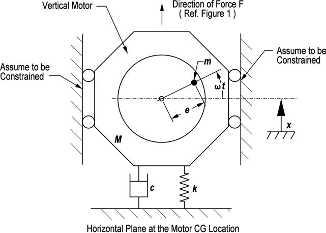
Figure 4. Model for rotating imbalance
From the relationships provided, the amplitude of vibration (X) caused by a rotating mass may be found using Equation 9, assuming a single balance plane acts at the motor CG.
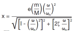 Equation 9
Where:
| m/M | = | The ratio of the rotating (motor rotor weight—m) to the motor weight (M)—dimensionless |
| e | = | The eccentricity of the rotating mass related to residual imbalance (in.)—NOTE: this is determined by the balance grade of the motor. Refer to ANSI S2.19 or ISO 1940/1. |
X
=
Values of: ![]()
are shown plotted versus values of ω/ωn and ζ in Figure 5.
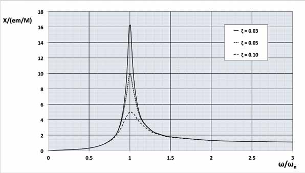
Figure 5. Vibration response for rotating imbalance
Modeling the Vibration Response at the Top of the Motor
The amplitude displacement (X) at the motor CG must be translated to the top of the motor for a mathematical model of top-of-motor expected vibration. This is accomplished using Equation 5, replacing X for y (see Equation 10).
![]() Equation 10
Equation 10
Where:
b = The distance (in.) from the motor CG to the top motor bearing vibration measurement location (see Figure 1)
In this case, the force (F—pounds) is the effective force due to imbalance that may be determined in a simplified manner as follows, assuming the motor center of gravity and the motor rotor center of gravity are in the same plane (see Equation 11).
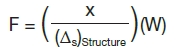 Equation 11
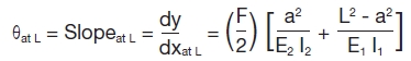
In Equation 11, X is determined with Equation 9, using the structure static deflection from Equation 6, and W is the motor weight. Substituting Equation 11 into Equation 6, the slope (θ) at the motor CG, while subject to the effective imbalance force, may then be calculated using Equation 12.
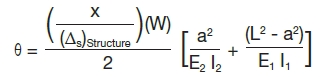 Equation 12
This simplifies to Equation 13.
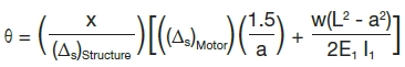 Equation 13
The peak amplitude at the top of the motor (in.) may be calculated by using the results from Equation 13 in Equation 10. Note that the peak-to-peak amplitude is twice the value of (X)top. Therefore, it can be seen that the peak-to-peak displacement amplitude (double amplitude displacement—in Mils) at the top of the motor, occurring at the frequency of the operating speed (comparable to filtered vibration), may be calculated using Equation 14.
![]() Equation 14
Equation 14
Because the vibration occurs at a discrete frequency, the result may be converted to units of velocity (inches per second) or acceleration (g) using commonly accepted industry methods.
It should be noted that this mathematical model most likely provides an order of magnitude approximation of the expected vibration. In using this predictive model in the preconstruction stage (as yet there has been no opportunity for impact testing in the field), the reader is cautioned that the results obtained are obviously subject to the accuracy of the input information and the stated assumptions.
For example, the actual motor reed frequency value can differ from the stated value if the stated reed frequency was not determined from impact testing of the actual motor used. The determination of accurate pump head effective moment of inertia in the preconstruction stage using equations can be difficult, greatly affecting the results. Still, this model may prove useful in providing practical insight for future studies of empirical data and methods as appropriate acceptance criteria and recommended practices are contemplated, and it is offered as a tool in this context.
Example
Consider the following example:
Inputs
125-horsepower, 885-rpm motor
| Δs | = | 0.008 in. (Motor reed frequency = 2,100 CPM) |
| M | = | Motor weight = 2,300 pounds |
| m | = | motor rotor weight = 720 pounds |
| e | = | 0.0028 = eccentricity from ANSI S2.19 for balance grade G6.3 assumed |
| a | = | 21 in. |
| b | = | 30 in. |
| L | = | 75 in. |
| E1 | = | 29,000,000 in. |
| I1 | = | 557 in.4 |
| ζ | = | 0.03 |
Calculated Results
Static deflection of the structure Δs = 0.02758 in.
Structure reed frequency = 1,130 CPM
Amplitude X at the motor CG = 0.00138 in.
Slope at the motor CG = 4.7036 x 10⁻⁵
Amplitude Xtop at the top of the motor = 0.00279 in.
Vibration at the top of the motor at the frequency equal to the operating speed = 5.6 Mils P-P
Bibliography
1) Thomson, Theory of Vibration with Applications, 4th Edition, Prentice Hall, 1993.
2) NEMA MG 1-2003
The author would like to thank Tom Angle of Hidrostal AG and Bill Marscher of Mechanical Solutions, Inc., for providing helpful comments in producing this article.