


"Understanding Factors That Cause Shaft Failures," June 2007
Click here for full article.
We are facing an issue in the twin screw pumps which pump mill base product intermediate of paint. The drive shaft and the non-driven shaft breaks. The breakage occurs randomly, like near the bearing end and at the center of the shaft as well. What could be the cause for such breakages?
Can the shaft break due to cavitation? Can you suggest something on this?
Arun Ramakrishnan
Gene Vogel, EASA, responds:
Cavitation in the pump can cause erosion to the surface of the rotors (screws). The erosion will create points of stress risers which could initiate a surface crack that propagates to a complete break of the rotor. Such a failure would leave evidence of the surface erosion from the cavitation.
The location of the rotor break would also originate on the surface of the rotor exposed to the pumpage. If the break occurs elsewhere on the rotor, or if there is no evidence of cavitation on the surface of the rotor, then cavitation was not a contributing factor.
Sealing Sense, August 2008
Click here for full article.
In the August 2008 “Sealing Sense,” you described the throat bush and its function in detail. What is the recommended standard for throat bushing clearance?
In an API 610-BB pump with a double-suction impeller running in liquid propane application (23 bar, 70 degrees C), we face seal puffing issues due to a
lack of vapor pressure margin. Based on the vapor pressure chart inference, we have to pressurize the stuffing box or cool down the fluid.
However, the site conditions do not have the provisions for further cooling. We are planning to improve the stuffing box pressure by reducing clearance, but we do not have a standard for that.
Could you please guide me in how to choose the right clearance? Any standard or calculation formula would help to find out a solution. Thanks for your support.
Kahlifa Jaleel Anver Pasha
FSA responds:
Much more information on the system and environmental conditions are needed to provide a complete and thorough recommendation.
However, running a liquid propane pump under the conditions of 70 degrees C and 23 bar (if these are indeed the output criteria) is far from ideal as the vapor pressure at this temperature, calculated from Antoine Constants, should be 24.9 bar. This would mean that there is a larger problem than just the potential for flashing of the propane at the seal faces. There could be problems of flashing anywhere in the system and resultant mixed-flow pumping.
You do not state what type of seal or flush plan is currently in use or if the criteria were indeed measured in the seal chamber or at pump discharge. Given this, the following are recommendations based on the assumption that you provided seal chamber pressures and temperatures and not pump discharge.
One possible solution would be to use an API 682 Plan 21 to reduce the temperature of the flush to a point another 15 degrees C lower than is currently being achieved, to obtain the 30 psi vapor pressure margin that is recommended in the API standard.
However, this requires that there is sufficient pressure in the discharge line of the pump to do so. It is not clear if this is the case.
Closing up the throat bushing clearances will require knowledge of:
• The diameter of the shaft at the position of the throat bushing
• The length of the present throat bushing
• The suction pressure on the impeller side of the throat bushing
• The size of the orifice used in the discharge line to determine the flow rate that can be accommodated
The flow through an annulus can be calculated using the flow formula for two flat plates and setting the width equal to the circumferential diameter of the rotor. The formula is below:
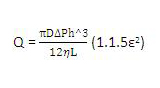
Where:
D = Shaft diameter
ΔP = Pressure drop across the bushing (pressure in chamber – pressure at the impeller case)
h = Radial clearance height (Bushing ID – D)/2
η = Dynamic viscosity of fluid at anticipated temperature
L = Length of the bushing
ε = Radial eccentricity (ε = 0 for fully concentric conditions)
and then solving for the variable required clearance versus chamber pressure.
This is easier than using the more exact formula for flow through an annulus. Where the result for the formula gives an unfeasibly small clearance, then consider placing a positive pumping composite bushing, with suitable helically grooved outer diameter, on the shaft and trim its OD to suit the required flow restriction to maintain chamber pressure.
It should be born in mind that the throttling effect caused by the throat bushing clearances or pumping will reduce the flow through the seal chamber. This could cause the temperature of the propane in the chamber to be increased further due to viscous flow, which can further exacerbate the flashing problem.
My genuine recommendation would be to use a reputable mechanical sealing and/or pump system OEM (as this may not be just a seal issue) and follow its recommendations.
Parallel—and Not So Parallel—Operation, June 2011
 Can you please explain how to calculate the flow of three pumps of equal capacity running in parallel?
Sarfraz Ahmad, Mechanical Engineer
Saudi Consulting Service
Lev Nelik responds:
There are several articles I published on pumps in parallel operation. In fact, the recent one is in the June issue of Pumps & Systems: www.pump-zone.com.
Also, I recommend attending one of my Pump School sessions where this (including construction of the combined multi-pump curve) and other pump topics are discussed in depth.
Newtonian and Non-Newtonian Fluids, August 2011
Click here for full article.
In response to your parting quiz in the August issue of Pumps & Systems: Why is a "typical" rule-off-thumb that centrifugal pumps do not operate well above the magic number of 500 centistokes viscosity?
I suspect that about 500 Cst is the vicinity at which the pump efficiency correction falls rapidly towards zero, which causes the needed horsepower to increase rapidly beyond what the actual driver’s horsepower can handle. Pump efficiency correction falls off much faster than either head correction or flow correction.
Thomas J. Hill, P.E., Lead Engineer
Foster Wheeler Upstream Flow Assurance and
Hydraulic Consulting
Lev Nelik Responds:
Excellent, Tom! At about 500 cSt efficiency begins to reach a 50-percent reduction correction factor (per HI charts, shown in the article) and continues to decline from there on.