


Cavitation in pumps is a well known but unwelcome phenomenon. When imploding bubbles of pumped product undergo rapid phase transformation from liquid to vapor state, and then back to liquid, the damage to internal components can be significant and severe. Hydraulic instabilities associated with cavitation (1) can create pressure pulsations and vibrations that can damage seals, bearings, couplings and internal rubs.
In most cases, cavitation-especially when fully developed-is accompanied by clearly audible noise and high vibrations. This article, however, describes a rather unusual cavitation situation without the typical audible noise or significant vibration levels, yet the pump was in a fully developed state of cavitation with a complete loss of differential pump head. Furthermore, this happened to one of the two pumps operating in series. Neither pump experienced this problem when operating by itself. The root cause was found only after analyzing the full spectral vibration signatures of both pumping units.
System Description
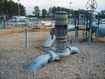
The system consisted of two multistage horizontally split centrifugal pumps at a pumping main booster station (denoted as stub line: "SL"), assisted by a single stage centrifugal auxiliary suction booster pumps (stub line booster: "SLB"). See Figure 1.
 |
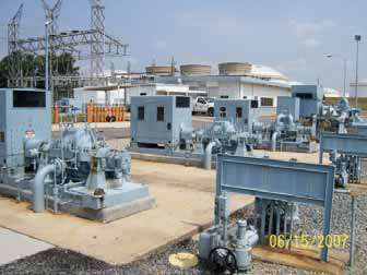 |
Figure 1. Stub line auxiliary suction booster pump (left) in series with the main stub line booster pumps
Depending on the flow requirement, one or both of the SL pumps operated. The piping arrangement was such (Figure 2) that either SL #1 or SL #2 can operate. The auxiliary suction booster pump operated continuously and generated suction pressure of approximately 75 psig for the first SL pump.
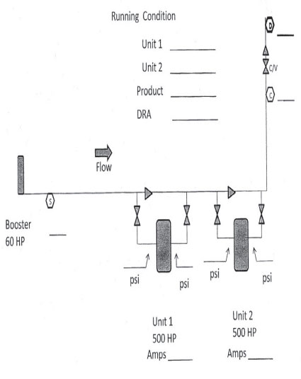
Figure 2. Set-up diagram
Figure 3 illustrates the hydraulic effects of operating a single pump versus two pumps in series, as well as illustrates the problem. Each pump normally operated at the intersection (2) of its head-capacity curve [Head(1)], producing about 800 gpm at 1,480 ft of head. This condition was verified.
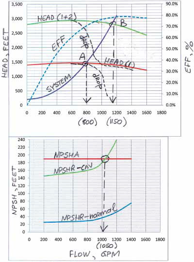
Figure 3. Hydraulic characteristics of a single pump and two pumps in series
Two pumps, running together, would be expected to operate at the intersection of the combined two-pump curve [Head(1+2)] and the same system curve, at 1,150 gpm and 2,800 ft. However, this was not happening. Instead, pump #2 continued to generate pressure, while developed head for pump #1 dropped to almost zero.
A faulty unit check valve was initially suspected, but inspection revealed no check valve problems.
Both units were part of a predictive maintenance program in which overall and full spectral vibration readings were taken at regular intervals. The historical operational and vibration data for these two units was also maintained (3). A review of the vibration trends (Figure 4) did not reveal a trend that would suggest a gradual deterioration of the mechanical condition of the pump.
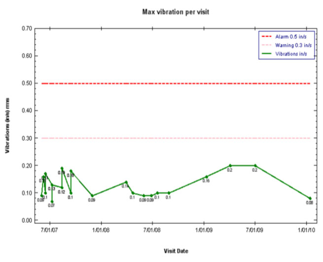
Figure 4. Vibration trends, overall RMS values
A more detailed review of the overall records of vibrations, flows and pressures, however, revealed that the two pumps were able to generate higher pressure in the past. The inability of the first pump to produce pressure in serial mode was a recent phenomenon.
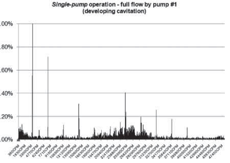
At this point, a detailed, full vibration spectral analysis was performed to aid in finding the root cause of the problem. Figure 5 shows a vibration signature for pump #1 operating by itself as well as in series with the second pump.
 |
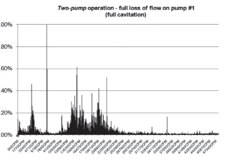 |
Figure 5. Pump #1 operating by itself (left) and with the second pump in series (right).
The analysis showed that pump #1 operated at a slightly cavitating condition when running by itself, as indicated by the slightly higher vibration noise levels around the five to nine times running speed frequencies. With the second pump operating, however, the cavitation noise became distinctly more noticeable in the full range of frequencies but especially around running speed and in the three to seven times running speed range. Even though this cavitation was neither clearly audible nor present in the overall vibration level, it was distinctly detectable in the full spectral analysis.
Furthermore, the full spectral analysis showed that the fundamental one and two times harmonics did not indicate any unbalance or misalignment problems with the unit in either mode of operation, with the only issue of concern the clear evidence of fully developed cavitation in the higher frequency harmonics.
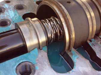
This pointed to a possible presence of some sort of obstruction at the inlet area of the casing of the first pump, most likely at the impeller eye area. Upon disassembly, it was confirmed that a spiral gasket of the upstream valve (before pump #1) failed and wrapped itself around the shaft at the eye of the first stage pump impeller. Figure 6 shows what it looked like when the pump was disassembled.
 |
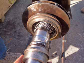 |
Figure 6. Gasket debris trapped at the inlet of the first stage impeller of pump #1
The blockage created by the wrapped spiral gasket at the impeller eye caused pressure drop and an increase of fluid velocity (reduced flow rate) to the impeller. This is illustrated in Figure 3, where a non-blocked impeller had a significantly lower NPSHR, allowing each pump to easily achieve 800 gpm flow. The blocked impeller NPSHR was significantly higher, yet still sufficiently below the NPSHA=190 ft, thus allowing each pump to achieve the 800 gpm. Beyond that, however, the elevated NPSHR curve of the blocked impeller crossed the NPSHA near 1,050 gpm, so pump #1 was unable to run out any further and stalled due to cavitation. After which point, only pump #2 developed head at only slightly higher flow (below 1,150 gpm).
Both phenomena caused a local pressure reduction that resulted in cavitation, even though the suction pressure was above the NPSHR for the pump. Interestingly, due to the relative circumferential uniformity (wire type evenly distributed) of the blockage, no significant unbalance (as, for example, would have been the case with a bolt entrapment) was created, and was not easily detected by the overall vibration levels.
The pump's internal components were then thoroughly cleaned and inspected prior to reassembly to ensure no further damage was incurred. Subsequent tests and vibration readings did not reveal any mechanical issues with the pump, and normal operating flows and pressures were once again achievable.
Summary
This case study reaffirmed the validity and importance of the proper use of vibration analysis methods. With proper vibration analysis and trending, application of hydraulic principles and a good understanding of the relationship between NPSHR, NPSHA (4), flow and pressure, a good insight into pump operation can be achieved, problems prevented and money saved. In this case, check valve inspection could most likely have been avoided with the more detailed analysis of past operating history, vibration trends and a full spectral vibration analysis.
Reliability oriented methods and close interaction between the operating, reliability and analysis groups-not to mention a proper understanding of engineering basics and use of proper diagnostic tools-have significantly benefitted the company.