


Q. What is a balanced mechanical seal, and when is it usually used?
A. Balancing a mechanical seal involves reducing the effective forces on the seal faces. A general rule is to use a balanced seal when seal chamber pressures are above 1,380 kPa (200 psi). Each application should be reviewed because the seal faces are affected by pressure, rotational speed, temperature and the properties of the liquid being sealed. At higher pressures or speeds, ensuring that an adequate lubricating film builds up is important. This is done by using a mechanical seal with a balance between 60 and 90 percent.
See figure 5.12.
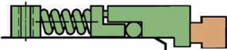
Figure 5.12. Balanced seal
The hydraulically loaded area is 10 to 40 percent smaller than the sliding surface area, and the closing force is reduced to the same extent. This measure increases the leakage rate because balanced seals tend to have higher leakage rates than unbalanced. Each mechanical seal is a compromise between:Ideal liquid friction in the sealing gap (as, for example, in a balanced seal) with the advantages of lower power consumption and increased service life but the disadvantage of higher leakage.
Mixed friction (as, for example, in an unbalanced seal) with shorter seal life as a result of increased friction but with lower leakage; see Chapter 4 of the Mechanical Seals for Pumps: Application Guidelines, published by HI, for more details on seal face balancing
Q. What is a pusher type seal, and what are the advantages of this design?
A. This is the broadest classification. It is determined by the secondary sealing element used in the flexible portion of the seal.
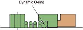
Figure 5.8. Pusher type seal
In a pusher type seal, the secondary sealing element moves axially to compensate for wear, vibrations and movement of the shaft. Several types of secondary elements are used, most commonly O-rings, wedges and spring-loaded polymer seals.In the non-pusher seal, the secondary sealing elements include bellows (elastomeric compounds, PTFE or metal). The convolutions of the bellows compensate for wear, axial movements and vibrations.
The application fields of both seal types are wide and may overlap. The most apparent distinction is the pressure limit. Pusher type seals cover the entire pressure range of mechanical seals up to and exceeding 20.7 MPa (3,000 psi). Non-pusher seals are typically limited to 7 MPa (1,000 psi) for elastomeric bellows and 2,070 kPa (300 psi) for metal bellows. The last type is popular for sealing of hot fluids without external cooling.
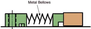
Figure 5.9. Metal bellows seal
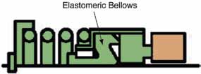
Figure 5.10. Elastometric bellows seal
Q.What is an energy efficient method for controlling the rate of flow in pumping systems?
A. Many pumping systems require a variation of flow or head. Either the system curve or the pump curve must be changed to get a different operating point. Where a single pump has been installed for a range of duties, it will have been sized to meet the greatest output demand. It will, therefore, usually be oversized and will be operating inefficiently for lower rate of flow duties.
Energy cost savings can be achieved by using control methods that reduce the power to operate the pump during reduced demand. In cases where interruption of flow can be tolerated, on/off control may be the most energy efficient option.
Varying pump performance by speed change is often an efficient control method. Figure 4.14 shows the energy consumption of other popular control methods when compared to variable speed control. More pump control principles and control examples can be found in Variable Speed Pumping: A Guide to Successful Applications.
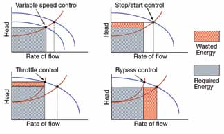
Figure 4.14. Energy consumption
Typically, variable frequency drive (VFD) upgrades are most viable when the systems are part of the original installation, when only the incremental premium must be justified. However, some installations can take advantage of the possible power savings provided by VFDs.
The typical VFD system today is a squirrel-cage induction motor fed from a VFD. The most common VFDs use insulated, gate, bipolar power transistors (IGBT) to create the voltage source pulse width modulation (PWM) to generate the variable voltage frequency for the motor. PWM/IGBT drives have the best overall performance, with high power factors throughout the speed range and are the most common type for small- and medium-horsepower motors. They generate low-speed torque, quiet motor operation and improved low-speed stability.
PWM/IGBT drives do stress the motor and drive cable, due to the fast output voltage rises that cause voltage doubling in the feeder cable from voltage reflections. An impedance load reactor should be used on the load side of the VFD when the motor lead length exceeds 100 feet. VFDs are an efficient type of variable speed drive. The most recent generations of VFDs perform well and have few complications when properly applied and matched to the motor and electrical system.
The energy consumed by a pump varies as the third power of the speed. Therefore, a 50 percent reduction in speed will reduce the power consumed by as much as 80 percent, depending on the system head curve characteristics. It is then possible to match pump operating speed to the exact conditions of service without throttling.
Not all this horsepower difference is savings, however, because a variable speed device has its own losses. The efficiency of a VFD (inverter) is affected by operating speed, ranging from about 97 percent at 100 percent of rated speed to around 91 percent at 50 percent of rated speed (input frequency), for the latest generation of drives.
A VFD causes harmonic losses in the motor, due to imperfect sinusoidal waves from the VFD supplying the motor. These losses cause the motor to heat up, which is why the motor may need to be de-rated when running with a VFD. Inverter-rated motor windings are required for 440 volts and above.
VFD drives can generate stray motor currents. This may require grounding of the motor rotor and/or the use of a bearing with an insulating coating on the outer ring. Small electric discharges between the rolling elements and the bearing raceway can eventually damage (pit) the bearings and/or cause them to run hotter, especially with larger motors over 100 kilowatts (150 horsepower).
Pumps & Systems, November 2011