


Final Article in a 14-Part Series
Suction-Side System Design
Centrifugal Pumps
Figure 1 shows most of the features discussed below.
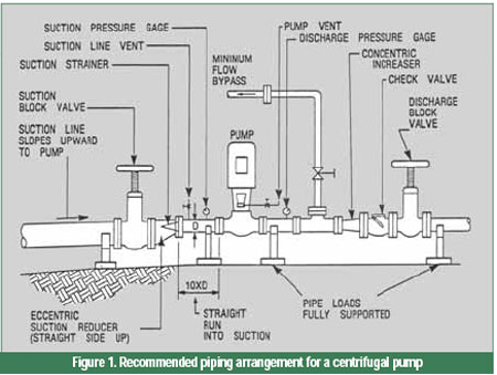
Straight Run Into Suction
For satisfactory operation, a centrifugal pump requires a uniform velocity profile of fluid entering the impeller. This is more critical for pumps with high suction specific speeds and pumps with end suction nozzles. A swirling or distorted velocity profile can cause problems. Therefore, no short‑radius elbows (or tees) should be used near the pump. The pump's suction nozzle should be preceded by a straight run of pipe, about 10 pipe diameters in length. A longer straight section may be required if turbulence is severe or velocity is high (more than 10 ft/s).
The author is aware of one installation that successfully uses long-radius, tapered elbows at pump inlets, instead of straight runs. (A converging nozzle has a significant stabilizing effect on flowing fluid.)
Location and Size of Block Valve
The suction block valve should be line size. Since the line is almost always larger than the pump nozzle, the suction valve must be placed before the reducer.
Sloping of Suction Lines
Overhead suction lines should slope downward to the pump to allow draining of the suction system through the pump. Horizontal or below‑grade suction lines should slope upward toward the pump to prevent the collection of gas at any point in the line. A gas pocket increases the friction loss, and will sometimes cause gas to move as a slug into the pump. It is better to have free gas pass through the pump continuously, in small quantities.
Suction Strainer-Shape and Flow Area
Unless the suction system contains a permanent filter, a temporary conical strainer may be provided in the suction pipe for plant start‑up. The included angle of the cone should not exceed 45 deg, and the free flow area of the strainer should be at least three times that of the piping. This "witch's hat" should point upstream. Suction pressure must be closely monitored and recorded to determine if the strainer is becoming plugged. If suction pressure drops too low, the strainer must be removed and cleaned. If it cannot be ensured that a strainer will be kept clean, it should not be installed. A pump will often be damaged more severely by starving the suction than by passing solids.
Suction Reducer-Concentric and Eccentric
For horizontal‑inlet pumps, the reducer at the pump should be eccentric, with the straight side up. This avoids the creation of a high point in the piping where gas can collect. For top‑inlet pumps, the reducer may be concentric or eccentric, as required to obtain clearance with the discharge piping.
Suction Gauge
A gauge should be provided at the pump suction. Although a gauge connection in the pump nozzle is occasionally used, turbulence and non-uniform velocity distribution make this point less desirable. More accurate readings are obtained in the suction pipe, after a section of straight pipe. There should be no fitting or valve between the pump and gauge connection.
Vent Locations
Vents should be provided in the suction piping and at the high point of the casing to allow priming the pump prior to start‑up.
Minimum‑Flow Bypass
Every centrifugal pump that can be operated too near shut‑off, should be provided with a minimum flow bypass. The bypass should be sized to pass the minimum flow that the pump manufacturer recommends or these articles have established. The bypass line should return to the suction vessel. It should not dump back into the suction line.
Reciprocating Pumps
Because of the pulsing flow, the design of a suction system for a reciprocating pump requires more care than for a centrifugal pump. Improper design has often resulted in vibrating, noisy systems. Pulsations may be severe enough to damage instrumentation, system components and pump components.
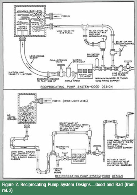
The following lists provide system design guidelines (2), as illustrated in Figure 2:
A. The suction vessel should:
- Be large enough to provide sufficient retention time to allow entrained gas bubbles to rise to the liquid surface.
- Contain a weir plate to force gas bubbles toward the surface, with its top sufficiently below minimum tank level to avoid turbulence.
- Have feed and return lines enter below the minimum liquid level.
- Include a vortex breaker over the outlet (pump suction) line, or have sufficient submergence to prevent formation of a vortex.
B. The suction piping should:
- Be short and as direct as possible.
- Be one or two pipe sizes larger than the pump suction connection.
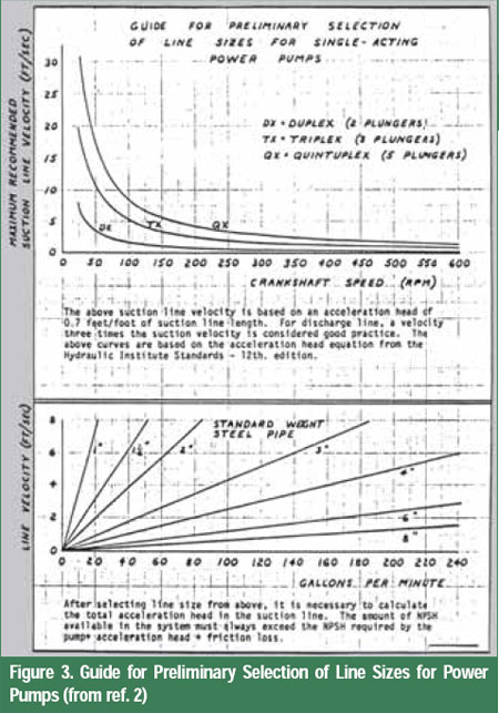
- Have average liquid velocity less than values from curves in Figure 3 (typically about 2 ft/s).
- Contain a minimum number of turns. Necessary turns should be accomplished with long‑radius elbows or laterals.
- Be designed to preclude the collection of vapor in the piping. (There should be no high points, unless vented.)
- Be designed so that NPSHA, allowing for acceleration head, exceeds NPSHR.
If acceleration head is excessive, include a suitable suction stabilizer, bottle or pulsation dampener located in the suction pipe, adjacent to the liquid end.
- Contain a full opening block valve so that flow to the pump is not restricted.
- Not contain a strainer or filter unless regular maintenance is ensured. (The starved condition resulting from a plugged strainer can cause more serious damage to the pump and system than solids can cause.)
If You Do Not Have Enough NPSHA
Ways to Increase NPSHA
If it is necessary to increase a system's NPSHA, one or more of the following steps may be employed:
- Raise the level of the liquid in the suction vessel.
- Cool the liquid (after it leaves the vessel).
- Reduce the losses in the suction line by reducing its length, increasing its diameter, reducing number of fittings, etc.
- Install a booster pump.
- With a reciprocating pump, or pulsating rotary pump, install a bottle or suction stabilizer in the suction line adjacent to the pump.
Ways to Reduce NPSHR
If the pump is in the selection stage, one or more of the following options may be employed to reduce the NPSHR:
- Use a double‑suction impeller.
- Use a larger pump.
- Use a lower‑speed pump.
- Use an inducer (a small axial‑flow impeller built into the eye of the main impeller).
- Install the pump at a lower elevation.
- With a vertical turbine pump, lower the first‑stage impeller (make the pump longer).
All of the above will normally increase the initial cost of the pump and/or installation. Options two and three will also likely result in higher operating cost due to lower efficiency. Option two may result in a pump operating in the hydraulically unstable range.If the pump is already installed, one or more of the following options may be employed to reduce the NPSHR:
- If operating near or beyond the BEP, reduce pump capacity.
- If operating near shut‑off, increase pump capacity (with a bypass if necessary).
- Reduce wear ring clearances.
- Reduce seal flush flow.
- Vent the seal chamber (stuffing box) back to the suction vessel.
- On a horizontal multistage pump with a balancing drum, pipe the balancing line back to the suction vessel. The valves in this line must be locked open.
- On a vertical multistage pump, pipe the bleed‑off line, from the throat bushing, back to the suction vessel. The valves in this line should be locked open.
To Quieten a Cavitating Centrifugal Pump
If a centrifugal pump sounds as if it is pumping gravel, if the system can tolerate it and if no other solution is readily available, inject about ½ percent (by volume) air (or other gas) just upstream (into the inlet) of the pump. Experiment to see how little air is necessary to obtain quiet operation. (Do not try this with a reciprocating pump!)
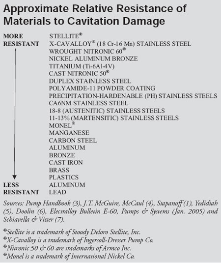
Resistance of Materials to Cavitation Damage
Because cavitation is, in a practical sense, unavoidable in many pumps, you may need to upgrade the materials of impellers, casings and/or wear rings in centrifugal pumps, or plungers, valves and related components in reciprocating pumps to reduce cavitation damage.
If cavitation is shortening the life of a pump's components, the list below, arranged with higher cavitation‑resistance on top, may be helpful in selecting a material that will provide longer life. Some authors show the materials in a slightly different order, so the order in the following table should be considered approximate.
References
1. Stapanoff, A.J., Centrifugal and Axial Flow Pumps, John Wiley & Sons, Inc., 1948.
2. Henshaw, Terry L., Reciprocating Pumps, Van Nostrand Reinhold Co., Inc. 1987.
3. Karassik, I.J., et al, Pump Handbook, McGraw-Hill Book Co., New York, NY, 1976.
4. McCaul, Colin, "An Advanced Cavitation Resistant Austenitic Stainless Steel for Pumps," 1996 NACE International Confrerence-Paper #415.
5. Yedidiah, S., "Compare Your Low-NPSH Pumps Carefully", Power, Feb. 1972.
6. Doolin, John H., "Judge Relative Cavitation Peril with Aid of These Eight Factors", Power, Oct. 1986.
7. Schiavello, Bruno and Visser, Frank C., "Pump Cavitation-Various NPSHR Criteria, NPSHA Margins, and Impeller Life Expectancy", International Pump Users Symposium, Houston, Texas, USA, 2008.