


Q. We have an application for pumps handling hot oil at 700 deg F. What special care should we take in selecting and installing such pumps?
A. Pumps for handling oils within the range of 150 deg C to 450 deg C (300 deg F to 850 deg F) are commonly termed hot oil pumps.
It is important that sufficient NPSH be available, as the liquid is almost always near the boiling point.
Provision should be made to allow self-venting of vapors from the impeller eye by venting the suction eye of the first stage except where the suction nozzle is in a vertical upward position. The stuffing boxes and bearing housings should be provided with cooling jackets.
The glands should be of the smothering type. If packing conditions require seal oil, lantern rings-together with the necessary pipe connections-should be provided. During operation, the seal oil pressure in the lantern ring should be held to a minimum of 175 kPa (25 psi) above stuffing-box pressure. Mechanical seals must be chosen specifically for the oil, temperature, pressure and speed.
The materials used for the construction of hot oil pumps should have a uniform coefficient of expansion and should be selected with particular reference to the oil's corrosive nature, as well as the actual pumping temperature.
Due to the high pumping temperature, the pump support should be arranged in such a manner to permit expansion of the pump casing without adversely affecting the coupling alignment.
API Standard 610 Centrifugal Pumps for General Refinery Service may be used for more information.
It is important that the suction and discharge piping be supported to avoid pipe strains imposed on pump nozzles. The unit must be aligned at the operating temperature.
Q. Are there guidelines for the basic speed ratings for reciprocating power pumps?
A. Yes. However, conditions of installation and variations in design significantly influence the selection of speed. The values in Table 1 are intended to serve as guidelines for basic speed ratings based on pumping cold water.
|
Table 1
|
||||||||||||||||||||||||||||||||||||||||||||||||||||||||||||||||||
For an intermediate stroke length, speed may be interpolated.
Note that these speeds are intended only as reference points. Some manufacturers offer their pumps for operation at or above these basic speeds. Others recommend lower speeds.
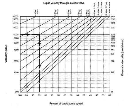
When a pump originally designed for low viscosity liquids is used for liquids of higher viscosity, basic pump speed reduction is necessary to obtain proper valve dynamics and prevent liquid separation. When viscosity ranges from 65 to 6,500 mm2/s (300 to 30,000 SSU), Figure 6.46 should be used to determine the appropriate reduction in basic speed. Only pumps specifically designed for high viscosity service should be used for liquids with viscosities above 6,500 mm2/s (30,000 SSU). See Section 6.3.2 in ANSI/HI 6.1-6.5 Reciprocating Power Pumps for details on the calculation of liquid velocity through valves.
A. A pumped fluid's viscosity typically affects pump ratings as follows:
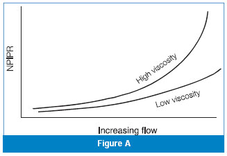
The net positive inlet pressure required (NPIPR) increases with increasing viscosity, as shown in Figure A.
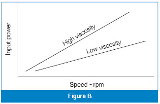
The required pump input power (Pp) increases with increasing viscosity, as shown in Figure B.
The maximum allowable pump speed (n) decreases with increasing viscosity.
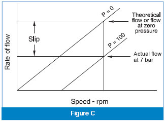
The pump slip (S), as shown in Figure C, decreases with increasing viscosity.
Exercise care in applying these generalities to non-Newtonian fluids, as the viscosity may change within the pump due to shear. When the apparent viscosity of a non-Newtonian fluid can be determined, then these generalities can be applied.
Because the exact relationship between viscosity and pump ratings depends on the pump design and on the application conditions, refer to the pump manufacturer's published data for a particular pump, or consult the manufacturer when considering viscous fluid pump applications.
Energy put into a fluid to overcome resistance to shear causes a finite temperature rise of the fluid. Consult manufacturers for recommendations on rotary pump applications involving fluids that are shear- or temperature-sensitive.
For more information about rotary pumps, see HI Standard, ANSI/HI 3.1-3.5 Rotary Pumps for Nomenclature, Definitions, Application and Operation.
Q. We are operating several centrifugal pumps on a water supply system. After one year of operation, the underside of the impeller blades exhibits pitting damage. The NPSH available (NPSHA) in the system is higher than the NPSH required (NPSHR) by the pump. What is causing this problem?
A. Cavitation typically causes such damage. NPSHA often must be greater than NPSHR by a factor of about two times or more to suppress the formation of cavitation bubbles.
Testing determines a pump's NPSHR to be that NPSH when the total head developed by the pump is reduced by 3 percent due to the blockage in the impeller by the cavitation bubbles. The complete elimination of cavitation bubbles may take NPSHA values as high as five times the NPSHR.
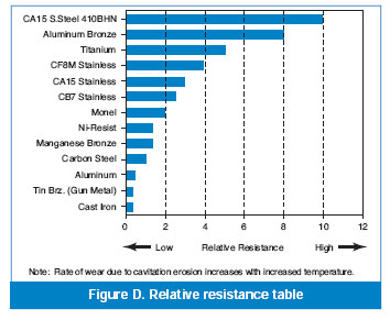
When pitting damage occurs, and the NPSHA cannot be increased, impellers made of more pitting resistant material may solve the problem. The results from research conducted by Cooper and Antunes have been tabulated in Figure A for some typical impeller materials.
Pumps & Systems, February 2010
HI is the largest association of pump manufacturers in North America. Hydraulic Institute, Inc., 6 Campus Drive, First Floor, North, Parsippany, NJ 07054, 973-267-9700