


In previous Pumping Prescriptions columns, we have looked at vertical pumps from various perspectives, including alignment, proper centering of the rotor shafting ("The Downside of Perfection in Vertical Pumps Repairs," May 2009) and the extent of an overhaul repair job ("Repair, Overhaul and Upgrade of Vertical Turbine Pumps," January 2008).
This month, we will look at why these aspects are so important to vertical turbine pump designs specifically, and similarities and differences between vertical turbine pumps and other pump types.
While the entire scope of centrifugal pumps is extensive, it is helpful, for simplification purposes, to consider the following general classifications:
a. End suction
b. Between bearings split case
c. Horizontal multistage
d. Vertical turbines
Both (a) and (b) are similarly different from both (c) and (d). Even more significantly, (a), (b) and (c) are similar in the transmission of their axial load, which is taken by the pump bearing and not a motor bearing. While some vertical turbine pumps feature an independent pump bearing pot, they are relatively rare. Whether the motor is hollow or solid shaft, the motor bearing takes the load, not the pump.
Vertical Turbine Alignment
Without a thrust bearing of its own and since it is positioned vertically, the pump's apparent symmetry might suggest that even a radial bearing is unnecessary. The pump bushings, placed along the shafting, are not true bearings, but rotor guides with relatively ample (as compared to a true hydrodynamic bearing) clearance between the rotor journal and the shaft. A true 4 in hydrodynamic bearing (oil lubricated, for example) typically has 0.004 in running clearance (one thousand per inch of shaft), while a guide ("bumper") bushing may have three to four times that amount-obviously with no ability to sustain a hydrodynamic loading.
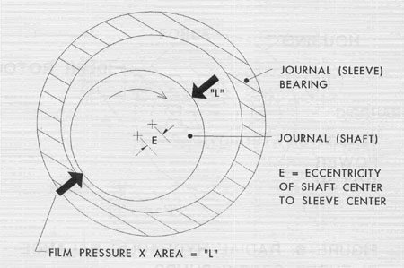
Figure 1
This is why proper alignment, choice of the materials for the shafting and its bushings, proper restoration of the fits and concentricity of the stationary parts during overhauls are important. Bushings, unable to withstand any substantial side loads, will quickly wear, or fail, if the shaft comes in close proximity due to incorrect eccentricity of the line piping fits. True hydrodynamic bearings need to be well-aligned, and vertical turbine pumps equipped with bumper bushings should likewise be aligned. Without proper alignment, many problems arise.
When one tries to grasp the uniqueness of vertical pump design, remember the manner in which the axial and radial loads are absorbed, as it may help in understanding the subject.
The Absence of Upper Flush-A Case Study
Another important aspect to address regarding vertical pump reliability is the absence of upper flush. The upper packing, if left without flush, may result in unexpected failure. If the eccentricity between the upper packing gland is not established properly, contact may result. If it happens and flushing water is not present, there will be no packing lubrication. The remaining water within the clearance between the sleeve and the mating bushing will quickly vaporize, pushing the packing out, breaking the gland and the bolts, and likely causing more damage.
Remember the components' concentricity is critical to successful pump operation. Concentricity is often as critical, if not even more critical, than dimensional tolerance. While proper clearances between components-for example, shafts (or their sleeves) to journals-are important, it is the components' concentricity (or lack of) that makes a difference between proper pump operation and failure.
While seemingly one of the smallest or least noticeable parts, the packing box is often a key element to a pump's successful operation. In this particular situation, the packing box (item 10 in Figure 2) did not appear to have been trued up (machined) or cleaned during the last repair, judging by its rusty appearance and rough steps and edges.
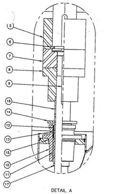
Figure 2
The packing box was likely sitting off-center.
The pump also arrived from the repair shop with the packings already installed. The correct procedure would be to first center the shaft within the packing box (the instruction manual should clearly illustrate this), then align the motor shaft to the pump shaft with the packing finalized. This procedure ensures proper concentricity of the shaft to the packing box, and of the box to the pump main casing to which the box is attached.
Apparently, a similarly incorrect installation procedure might have happened with other pumps at the facility. A sister unit had a motor sitting "off-lined" in an apparent attempt to align the shafts given the "tilted" (not centered prior to packing) pump rotor.
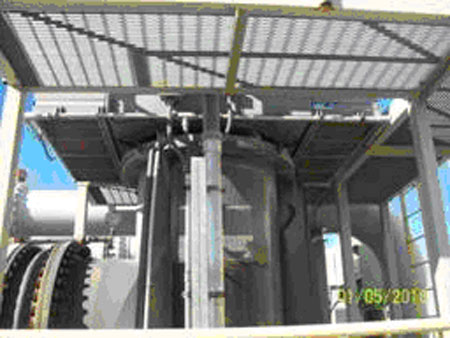
Figure 3
The situation was likely caused by similarly pre-packed pumps that arrived from repair shop(s) and were aligned to the motor in an eccentric state, as noted above. This causes the clearance between the shaft sleeve and bushing to be uneven, with one side likely coming too close and possibly contacting, especially if the shaft (may have) excessive runout.
The sleeve design arrangement in this example was likewise fundamentally problematic. As shown in Figure 2, it is inserted under the pump coupling and attached to the coupling with the setscrews recessed in the the sleeve's groove. Such arrangement is rare and confusing to the installation crew. The sleeve needs to be located axially without such dependency on the coupling. However, even as is, the actual installation did not engage the setscrews to the groove, and the sleeve ended up hanging free and supported (from following down) by the packing friction.
Finally, the arrangement did not have a lantern ring or flush piping to the packing, so no cooling and flushing was available.
Likely Scenario of Failure
Due to the combination of the issues with the repair and installation procedures, the head shaft sleeve made contact shortly after start up. This choked the flow to the packing from the pump, particularly since there was no flush water to compensate. Water above and in the tight space between the packing bearing (11) and sleeve (17) quickly heated and became vapor. As it continued to heat up, the vapor increased in pressure (like a pressure cooker), which then blew the packing out, bent the gland's bolts and pushed the gland off. The "puff of smoke" (steam) observed by the operators was likely the water vapor popping up. As the pump continued to run, the heat continued to expand the sleeves and soon caused seizure.
Recommendations to Avoid Such Issues
Document step-by-step repair procedure, including dimensioning of critical components, critical clearances, fits and eccentricities
Include in this procedure shaft run-out, at several (five) locations along the shaft, clearly stating the locations on a sketch
Document installation procedure (in addition to the existing IOM of the OEM), making sure centering of the rotor, alignment, packing, etc., is properly sequenced
Modify the design of the sleeve positioning, making it not dependant on the pump coupling
Illustrate the above with clear sketches, photos and simple instructions. Make sure repair report contains clear, simple, but sufficient illustration of the dimensions and clearances on a one-page sketch or drawing to accompany the report
Typically, flushed water is provided at least 15 psi higher than the packing box pressure. As raw water intake stations know, such arrangement keeps the sandy water from entering the box and wearing the sleeves and packing. While the abrasives are not an issue in this particular case, a higher pressure flush still forces the water into the pump, and not out, thus providing additional cooling and cleansing purpose. A lack of adequate flush water pressure and not having a lantern ring installed are, unfortunately, common reasons for missing flushing arrangement. At some installations, adding a booster flush circuit pump may help.
Pumps & Systems, March 2010