


Flow meters are necessary in the municipal world because utilities require accurate flow measurements for everything from chemical dosing to customer billing. The types of flow metering technologies are vast and depend on the accuracy required, water quality and line sizes.
Electromagnetic flow meters are a common choice because of the cost, reliability and turndown, among other considerations. Unfortunately, they require straight runs upstream of and downstream from the meter—typically five pipe diameters upstream and two diameters downstream—for reasonable accuracy. Other technologies are available, but they also require straight runs. In many cases, the straight runs are longer than those required of electromagnetic flow meters.
In-Valve Technology
A relatively new concept is adding a flow meter into the control valve to reduce the amount of additional equipment required to use the flow signal and control a valve in the line. Typically this would require a flow meter, a control valve, a valve positioner and a software program to achieve the flow control loop.
In-valve metering is particularly useful in applications in which a control valve is used and a flow signal would also be beneficial—for example, reservoir filling. It is also useful in applications in which there is not physical space for a conventional flow meter, such as pressure reducing valve stations. Typically, these in-valve meters fall into three main categories:
- In-valve turbine meter
- In-valve insertion vortex meter
- Calculated flow measurement using position transmitters and differential pressure transmitters that calculate the flow rate from a known position on the valve CV curve
Each technology has merit, but each also has its disadvantages. Turbine meters require clean water and maintenance. Vortex meters are prone to vibration effects (giving a flow reading when no flow is present) and plugging or damage because of foreign objects in the line.
When using the flow calculation method, accuracy depends on having a correct valve CV curve and the ability in the program to get a reading at any position along that curve as opposed to a fixed number of points along the curve. Because of the number of instruments required—differential pressure transmitter and position transmitter—the risk of the compounding of errors is also introduced. This is also the least accurate of the three measurement methods.
Accuracy should always be considered with any method. Current in-valve technologies are typically rated with a percent of full-scale accuracy. While they may report an accuracy of 2 percent, what does that really mean? The number quoted is important, but the statement after the percent sign is equally important. A percent of full scale meter, while accurate at full flow, can be dramatically different at low flow rates, which end users would expect to see in a flow control valve scenario.
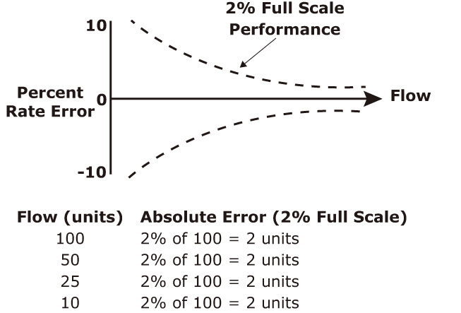 Figure 1. Full-scale meter accuracy
As shown in Figure 1, a 2 percent of full scale meter can still be within specifications at the low end flow rate of 10 units, with a reading of 8 to 12 units. This is +/- 20 percent accurate—a big difference from the 2 percent end users thought they had.
A better flow meter would have a percentage of reading accuracy (see Figure 2). This meter, at the low end flow of 10 units, is accurate from 9.8 units to 10.2 units, which is a much better proposition for accurate control.
New Technology
One valve company has recently partnered with a flow meter manufacturer to introduce a single point insertion electromagnetic flow meter installed into a control valve. This is a 2 percent of reading flow meter that has been flow profiled and tested in a National Institute of Standards and Technology traceable flow laboratory in Hemet, Calif. This means that the unit is guaranteed accurate to 2 percent of the reading throughout the specified velocity range. The flow meter has been profiled to match a specific valve. With this valve, it is ready for use directly out of the box.
The insertion probe extends into the flow stream, in one of the valve inlet connections and protrudes into the valve equivalent to 1/8 of the valve diameter size. It is a bullet nose, flow clean profile to eliminate clogging or build up. The unit can be installed on valve models from 4-inch to 36-inch valve sizes. It can be installed on either side of the valve on the inlet connection and only requires three pipe diameters of upstream clearance.
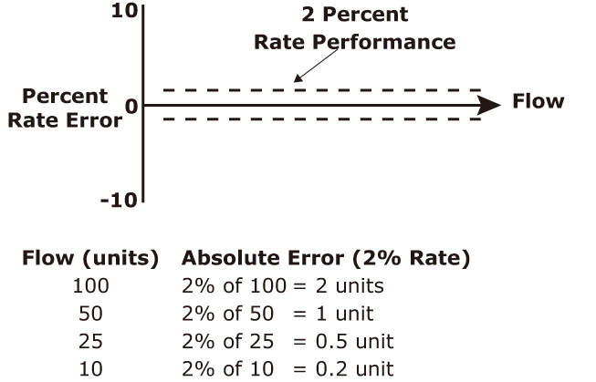 Figure 2. Flow meter with a percentage of reading accuracy
The sensor is rated for continuous submergence and is removable. It only protrudes from the valve 4.6 inches to 6.3 inches and only requires an 8-inch to 12-inch clearance for maintenance.
It is supplied with a convertor that provides an LCD readout screen and also gives a 4-20-milliampere output with four programmable digital outputs. P&S