


Last month, we discussed that the system (not the pump) dictates where the pump will operate on its performance curve. We also discussed “liquid personality” (the properties of the liquid) such as specific gravity, suspended solids, pH and viscosity and the mostly negative effects on the pump and system.
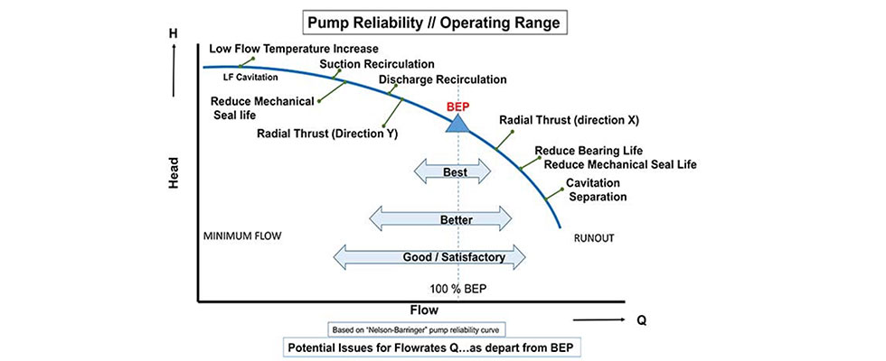
If you have been around the pump world for more than a few days, I am sure you have heard the term best efficiency point (BEP). In essence, all centrifugal pumps are designed for just one operating point of flow and head on the curve. This one design point for flow X and head Y is commonly referred to as the BEP or best operating point (BOP). All other possible operating points are, to some varying degree, a counter compromise with efficiency, cavitation, radial thrust (shaft deflection) and recirculation issues. Ignoring these stress issues will shorten the life of the bearings and mechanical seals, making the pump less reliable and more costly to operate.
If time and money were not an issue, the pump OEM would be happy to design and build a pump specifically for the user’s unique operating point. Yes, it does happen, but not very often.
Allowable Operating Region
Of course, most end users don’t have just one operating point—normally they want to operate in a wide area of the curve that is commonly referred to as a safe or allowable operating region (AOR). The presumption is that the end user knows where the pump is operating on its curve and fully understands that the pump will operate where the system curve compels it to perform.
If you are experiencing pump failures, perhaps the problem is that the pump was selected incorrectly and/or the system curve was miscalculated? Assuming the pump selection was the best choice compromise for the application, and since many pump applications require operation away from the design area of BEP, there are methods to manage the negative effects. All of the mitigation methods are burdened with the added cost of pump efficiency reduction, but that increased cost may often be an acceptable trade-off for reliability and reduced maintenance costs. You can explore the numerous methods to reduce or eliminate the negative effects with your pump salesperson, technician/engineer or a knowledgeable systems design person. If you have no means to determine the differential pressure across the operating pump, such as a set of simple pressure gauges or transducers, then your first check box on the road to pump reliability will be to install a set (one on the suction side and one on the discharge side) and then calculate where the pump is operating on the curve.
What’s the Big Deal With Operating the Pump Away From BEP?
The simple answer is that if you run too far right—that is, at or near the end of the curve—the pump will cavitate and the result will be high vibration levels that will damage the mechanical seal and bearings in quick fashion. The impeller may also suffer cavitation damage that is dependent on several variables not covered in this column.
As I often state in my role as the master of the obvious during my pump training classes, “the end of the curve …is the end of the curve.” If pump manufacturers thought you could or should operate there, they would extend the curve. Everyone wants more coverage, but the laws of physics keep getting in the way.
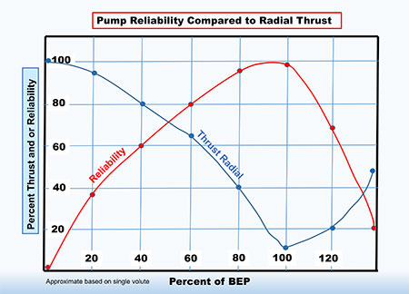
Another important factor to consider near the end of the curve is the radial thrust, which will increase exponentially as you depart from BEP and move toward runout. Depending on the shaft rigidity factor (L3/D4 ratio or think robustness factor), the shaft may deflect some amount. Shaft deflection is a dynamic bending of the shaft while in motion that occurs two times per revolution. Understand that a shaft rotating at 3,550 rotations per minute (rpm) will have 7,100 deflections per minute. Shaft deflection will damage mechanical seals and bearings. More importantly, excessive deflection can often lead to shaft cyclic stress fatigue and breakage. Also, be aware that the shaft would measure perfectly straight if you stopped and removed it from the pump. As I mentioned before, deflection is a bending phenomenon that may occur during operation. If the shaft is already bent and/or the impeller is out of balance, the situation is critically exacerbated. For more details, see my January 2021 column on radial thrust and my February 2017 column on shaft breakage.
Operating the pump to the left side of the curve also has negative consequences. When we state operating to the “left,” we mean operations between the BEP and shutoff (sometimes just abbreviated as SO). Shutoff is the point of no (zero) flow such as closing the discharge valve or a blocked system component. Operating near shutoff will also increase the radial thrust and deflect the shaft—the same phenomenon we discussed above at the far right side runout condition and with the same penalties. The only difference from the radial thrust experienced at runout (right) when compared to the left side of the curve is the thrust is now applied from the opposite side (180 degrees of opposition). The negative effects are the same.
Most pump manufacturers will advise you where the recommended minimum flow point is on the left side of the curve. This is frequently referred to as the minimum continuous stable flow (or allowable flow). Minimum continuous stable flow (MCSF) is defined as that flow rate below which the pump should not be operated for any length of time. What is not defined is the amount of time, and I would suggest minimizing the time as much as possible. The higher the pump energy (brake horsepower [BHP]) the shorter the time.
One rudimentary way to think about this is to convert the driver’s BHP to British thermal units (Btu), and then realize that much of that energy is working to heat the liquid in the pump casing while simultaneously the shaft is bending twice per revolution.
There are four factors to be calculated/evaluated when determining the acceptable minimum flow point. For this column, we will just examine the main two factors. The first is from a pump mechanical perspective: How much dynamic load from a radial and axial thrust perspective can the pump take? And the second is from a thermodynamic aspect: At what point does the liquid convert/flash to vapor? The pump OEM will determine a minimum continuous flow rate for the pump for both mechanical and thermal factors—the higher of the two will become the minimum flow rate for that pump. For more details, see my Pumps & Systems column from November 2015.
By Design, the System Must Supply the Liquid to the Pump
Stated another way, centrifugal pumps do not suck liquids. I mentioned in Part 1 of this series that most pump problems occur on the suction side of the system due to this misunderstanding about centrifugal pumps. “This is mostly due to a common misunderstanding that pumps will ‘suck’ the liquid into the pump—they do not. The suction portion of the system must supply the required energy to move the liquid to the pump; this is typically accomplished by gravity or atmospheric pressure.” (Some external source other than the pump.)
Note from a technical perspective that the pump impeller does create a small differential pressure directly in front of the impeller, but that energy level is in no way sufficient to overcome gravity and the friction required to initiate and sustain the flow rate. Also, note that liquids do not possess tensile properties, and so the pump is not capable of pulling the fluid into itself.
One way to describe the energy required on the suction side of the system at the pump suction flange is called net positive suction head available (NPSHa). I understand this is a return-to-pump-basics column and many neophytes will dismiss and ignore this uncomfortable subject for as long as possible. I would suggest that the sooner you can wrap your head around the subject, the better off you will be.
For reference and assistance, please refer to a detailed series of five columns I authored on this subject starting in July 2018.
NPSH: A Primer
Yes, the pun is intended. The pump OEM/manufacturer will design and test its pump to determine net positive suction head required (NPSHr).
That is, for several condition points on the pump curve there is a corresponding amount of energy required at the pump suction that must be satisfied by the system. It is the pump manufacturer’s responsibility to conduct this test and report/ publish the results in accordance with industry standards.
Conversely, for any given system design and corresponding flow rate, there will be an amount of NPSHa. It is the responsibility of the system designer to accurately determine/calculate the NPSHa. There must be more NPSHa than NPSHr, and the margin required will vary based on several circumstances not covered here but can be referenced in American National Standards Institute/Hydraulic Institute Standard 9.6.1 (2012).
If there is insufficient NPSH margin, the pump will cavitate and be short-lived. Cavitation is the formation of vapor bubbles in the liquid stream (normally just in front of the impeller) and then the subsequent collapse of those bubbles some distance along the impeller vane. Normally the bubbles collapse within the first 25% to 33% of the vane length. The bubbles will collapse on the underside (concave side) of the vane.
Next month, we will discuss suction and discharge recirculation, submergence and a few more basic pump topics.
A Note About MCSF
Note that for a given size pump, if one manufacturer states its minimum continuous stable flow is lower than another manufacturer, this does not mean it is necessarily a better pump. It may just mean the manufacturer is more conservative in its approach to reliability.
Notes on Cavitation
You may think the liquid is not hot enough to form vapor bubbles and likely it is not at ambient pressure, but remember from science class that you can boil water at room temperature if you reduce the pressure sufficiently. You can boil water at 70 F if you reduce the pressure to 0.363 absolute pressure (psia).
Do not confuse vapor bubbles with air bubbles. The collapse of entrained air bubbles in the liquid stream does little damage to the impeller. It is possible to air-bind the pump where the air bubbles block the flow of liquid. Vapor bubbles, on the other hand, possess high energy and can severely damage an impeller in a short period of time. Actual damage will vary with the energy level, liquid properties and impeller materials.
Just because you have adequate NPSH margin does not mean that there will be no cavitation or damage. Even with high margins, there may still be cavitation occurring, albeit probably not of a very destructive nature.
You may also see what appears as cavitation damage on the convex side (aka, the working side or high-pressure side) of the impeller vanes and this is typically due to recirculation cavitation. This damage is not due to insufficient NPSH margin, but to operating the pump in a nonstable region between BEP and approaching shutoff. The actual operating point (area) where this will occur is a function of the impeller’s suction specific speed (Nss). Nss in its simplest form is an expression of the design geometry for the suction side of the impeller. Consider the number of vanes, inlet vane angle, curvature and pitch of the vane, the amount of vane overlap and effective impeller eye diameter, to name a few factors.