


There are significant differences between flow meter technologies, with each type of device having its own advantages and disadvantages.
With a growing focus on corporate responsibility and sustainability, the monitoring of greenhouse gas (GHG) emissions is critical. Firms must ensure regulatory compliance while protecting assets, personnel and the environment. Another crucial concern is custody transfer, with increasing energy costs driving the need for improved fiscal metering of high-value products.
Common Flow Applications
In modern industrial plants, personnel need to make faster and better decisions by capturing, managing and analyzing data. These facilities rely heavily on flow processes, and thus accurate and reliable measurement technology is vital. Most plants have two flow measurement challenges: accuracy and cost. The goal is to correctly match the right flow meter to the right application to achieve the best performance for the lowest purchase price and total cost of ownership.
Popular Measurement Devices
Flow meters are excellent tools to measure, monitor and control the distribution of a host of fluids. The question is which technology to use.
Coriolis. Coriolis meters have a vibrating tube in which a fluid flow causes changes in frequency, phase shift or amplitude. The sensor signal is fed into the integrally mounted pc-board. The resulting output signal is strictly proportional to the real mass flow rate, while thermal mass flow meters depend on the physical properties of the fluid.
Coriolis flow meters directly measure fluid mass over a wide range of temperatures with a high degree of accuracy. Their unobstructed, open flow design is suitable for viscous, non-conductive fluids that are difficult to measure with other technologies. With no internal moving parts, Coriolis meters require minimum attention once installed. However, they are sometimes considered too sophisticated, expensive or unwieldy (see Image 1).
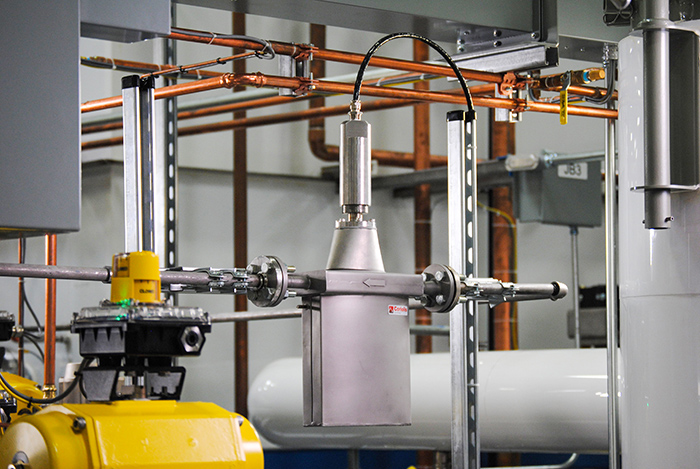 Image 1. Coriolis flow meters are designed to directly measure fluid mass over a wide range of temperatures with a very high degree of accuracy. (Images courtesy of Badger Meter)
Differential pressure (DP). DP meters measure the pressure differential across the meter and extract the square root. They have a primary element that causes a change in kinetic energy, creating DP in the pipe, and a secondary element measuring the differential pressure and providing a signal or read-out converted to the actual flow value. DP meters employ a proven, well-understood measuring technology that does not require moving parts in the flow stream and are not greatly affected by viscosity changes. However, they have a history of limited accuracy and turndown, as well as complex installation requirements
Electromagnetic. Electromagnetic meters use Faraday’s law of electromagnetic induction, whereby voltage is induced when a conductor moves through a magnetic field. The liquid is the conductor, with energized coils outside the flow tube creating the magnetic field. The produced voltage is directly proportional to the flow rate.
Electromagnetic meters will measure virtually any conductive fluid or slurry. They provide low pressure drop, high accuracy, high turndown ratio and excellent repeatability. The meters have no moving parts or flow obstructions, and are relatively unaffected by viscosity, temperature and pressure when correctly specified. Nevertheless, they have a propensity to foul, tend to be heavy in larger sizes and may be prohibitively expensive (see Image 2).
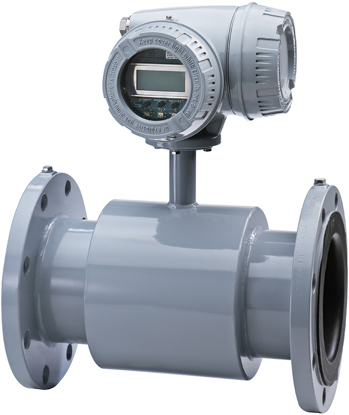 Image 2. Electromagnetic flow meters are compatible with virtually any conductive fluid or slurry found in industrial processes.
Positive displacement (PD). PD meters separate liquid into specific increments, and the flow rate is an accumulation of these measured increments over time. The rotational speed of a PD meter’s impeller is a function of the process flow. An internally coupled counter monitors the measuring element’s rotations to provide a volumetric recording of the flow total. PD meters are highly accurate and have one of the largest turndown ratios. They are easy to maintain since they have only one or two moving parts. Systems do not need straight pipe lengths, as they do with other metering approaches. However, PD meters require clean fluids and can be large and difficult to install.
Thermal mass. Thermal mass meters use a heated sensing element isolated from the fluid flow path. The flow stream conducts heat from the sensing element, which is directly proportional to the mass flow rate. The meter’s electronics package includes the flow analyzer, temperature compensator and a signal conditioner providing a linear output directly proportional to mass flow.
Thermal mass meters have a relatively low purchase price and are designed to work with clean gases of known heat capacity, as well as some low-pressure gases not dense enough for Coriolis meters to measure. The main disadvantage of thermal technology is low-to-medium accuracy, although suppliers have improved the capabilities of these meters in recent years.
Turbine. Turbine meters contain a freely suspended rotor, and the flow against its vanes causes the device to rotate at a rate proportional to flow velocity. A sensor/transmitter is used to detect the rotational rate of the rotor; when the fluid moves faster, more pulses are generated. The transmitter processes the pulse signal to determine the fluid’s flow. Turbine meters incorporate a time-tested measuring principle and are known for high accuracy, wide turndown and repeatable measurements. They produce a high-resolution pulse rate output signal proportional to fluid velocity, and hence to volumetric flow rate. Turbine meters are limited to use with clean fluids only. As a mechanical meter, turbines require periodic recalibration and service.
Impeller. Impeller meters are frequently used in large diameter water distribution systems. The device consists of a paddle wheel inserted perpendicularly into a process stream. The number of rotations of the paddle wheel is directly proportional to the velocity of the process.
Impeller meter attributes include: direct volumetric flow measurement, universal mounting, fast response with good repeatability and relatively low cost. Their performance suffers in applications with low fluid velocity. The meters are sensitive to flow profile. They can only be used in clean, low-viscosity media.
Ultrasonic. There are two types of ultrasonic meters: transit time and Doppler. Both designs detect and measure bidirectional flow rates without invading the flow stream. Ultrasonic meters are ideal for troubleshooting, diagnostics and leak detection. They can be used with all types of corrosive fluids, as well as gases, and are insensitive to changes in temperature, viscosity, density or pressure (see Image 3).
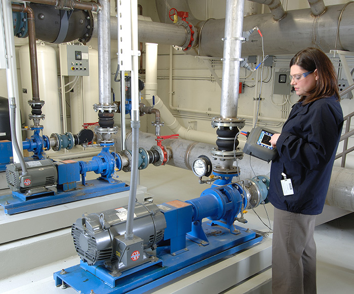 Image 3. Clamp-on ultrasonic flow meters can be used for troubleshooting a wide range of flow issues, from verifying the reading of another meter to monitoring flow systems over time.
Ultrasonic meters have no moving or wetted parts, suffer no pressure loss, offer a large turndown ratio and provide maintenance-free operation. Conversely, their precision becomes much less dependable at low flow rates. Unknown internal piping variables can shift the flow signal and create inaccuracies.
Variable area. Variable area meters are inferential measurement devices consisting of two main components: a tapered metering tube and a float that rides within the tube. The float position—a balance of upward flow and float weight—is a linear function of flow rate. Operators can take direct readings based on the float position with transparent glass and plastic tubes.
Simple, inexpensive and reliable, variable area meters provide practical flow measurement solutions for many applications. Most of these meters must be mounted perfectly vertical. They also need to be calibrated for viscous liquids and compressed gases. Their turndown is limited and accuracy relatively low.
Vortex. Vortex meters make use of a principle called the von Kármán effect, whereby flow will alternately generate vortices when passing by a bluff body. A bluff body is a piece of material with a broad, flat front that extends vertically into the flow stream. Flow velocity is proportional to the frequency of the vortices. Flow rate is calculated by multiplying the area of the pipe times the velocity of the flow. Vortex meters have no moving parts that are subject to wear, and thus regular maintenance is not necessary. Only clean liquids can be measured with this type of instrument. Vortex meters may introduce pressure drop due to obstructions in the flow path.
Oval gear. Oval gear meters use a PD meter design, whereby fluid enters the inlet port and then passes through the metering chamber. In the chamber, fluid forces internal gears to rotate before exiting the outlet port. Each rotation of the gears displaces a specific volume of fluid. As the gears rotate, a magnet passes a reed switch, which send pulses to the microprocessor in the register to change the LED display segments.
The latest breed of oval gear meter directly measures actual volume. It features a wide flow range, minimal pressure drop and extended viscosity range. This design offers easy installation and high accuracy and measures high-temperature, viscous and caustic liquids with simple calibration.
Nutating disc. In nutating disc meters, a disc attached to a sphere is mounted inside a spherical chamber. As fluid flows through the chamber, the disc and sphere unit wobble or “nutate.” This effect causes a pin, mounted on the sphere perpendicular to the disc, to rock. Each revolution of the pin indicates a fixed volume of liquid has passed. Nutating disc meters have a reputation for high accuracy and repeatability, but viscosities below their designated threshold adversely affect performance.