


Three 20-inch high service water pumps at the Huntsville Southeast Water Treatment Plant in Alabama are protected with hydraulically operated American Water Works Association (AWWA) C507 ball valves instead of typical swing check valves. Ball valves were selected by the engineer as a way to save energy. Also, the ball valve is equipped with features to monitor system operation and help prevent damage from equipment variations.
As a result, the pump discharge flow can be carefully controlled to prevent check valve slam and surges in the downstream 48-inch water pipeline (see Image 1). Because ball valves are slow-closing, quarter-turn valves, they are not subject to check valve slam. Also, when pipelines are several miles long, it is important for pump control valves to operate very slowly, over several minutes. The slow operation protects the pipeline from rapid changes in
fluid velocity when the pumps are started.
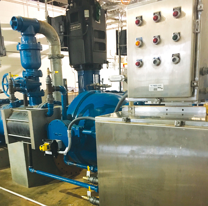 Image 1. Smart ball valve pump control system (Images courtesy of Val-Matic Valve & Mfg. Corp.)
On long pipelines, every 1 foot per second (ft/sec) of velocity change can create a 50 pounds per square inch gauge (psig) surge on top of the system pressure. Starting just one of the three pumps could boost the velocity in the 48-inch pipeline several feet per second, potentially causing a 200 psig surge. The solution is to control the opening and closing of the pump control ball valves slowly over 60 to 300 seconds using a hydraulic control panel powered by an oil accumulator supply system. The oil accumulator system provides 80 psig oil pressure for smooth and reliable valve operation, even after a power failure.
Ball valves not only prevent surges by closing slowly, but they also have equal-percentage inherent flow characteristics that help prevent surges on long pipelines. The equal-percentage characteristic states that for every percent change in valve position, there is an equal percentage change in the valve’s flow coefficient (Cv). This characteristic allows the valve to effectively control flow through a wide range of its operation. Looking at the geometry of ball valves, they have a seat on each end of the valve, resembling two valves in series, hence their wide operating range.
Energy Calculations
The ball valve is used for pump discharge applications because it can provide energy savings over the plant’s life. Most of the energy used at water plants is consumed for high service pumping costs to overcome the static head and friction losses of distribution systems. Head loss can be converted into an energy cost related to the pumping electricity needed to overcome the additional head loss from the valve using Equation 1.1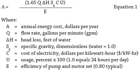
The energy consumption difference between two valve selections can be calculated by using the head loss difference between the two valves for the variable ΔH in the equation. For example, the difference in head loss between a 20-inch ball valve and 20-inch swing check valve operating at 10 ft/sec is approximately 2.5 feet of head.2 Therefore, assuming the pumps run 50 percent of the time with an efficiency of 80 percent and an electrical cost of 8 cents per kW-hr for 40 years, the following calculation can be made:
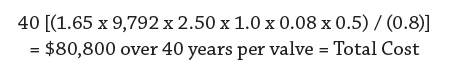
The calculation shows that the use of a 20-inch AWWA ball valve in the place of a swing check valve can save $80,800 per valve over the plant’s life—showing that valve selection can play an important role in energy savings.
Saving electrical energy also reduces the need for burning fossil fuels and creating greenhouse gases. On a national average, for every kW-hr of electricity used, about 1.14 pounds of CO2 emissions are generated. In the previous example, the use of a ball valve would result in savings of 575 tons of CO2 emissions per valve over the 40-year life of the system.
Valve Operation
The ball valve performs the critical function of an automatic check valve, so it needs to be reliable and tight-closing. The ball valve is powered by an oil-powered cylinder actuator built in accordance to AWWA C541, which requires specific materials of construction and production test to ensure a high level of quality and dependability.
The barrel of the cylinder is constructed of a lined fiberglass tube to prevent corrosion. The cylinder rod is hard chrome plated stainless steel to prevent wear and corrosion in the cylinder. The hydraulic cylinder is coupled to a quarter-turn, link-lever actuator to provide the required 90-degree rotation to operate the ball valve.
Mounted on the actuator’s top is a limit switch control unit that provides a remote signal for valve full-open and full-closed positions. The entire valve assembly was built and tested together in the factory in accordance with AWWA C507.
The valve’s hydraulic actuator is controlled by an oil-hydraulic control system consisting of a four-way solenoid valve that opens the ball valve when energized (see Image 2).
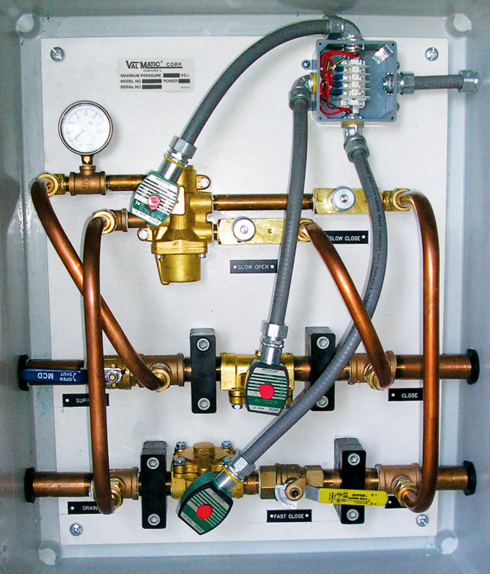 Image 2. Hydraulic control panel
Also included are two large two-way solenoid valves that are normally energized. But upon loss of electrical power to the pump station, they allow rapid flow of supply media to the cylinder actuator to rapidly close the ball valve in 10 to 30 seconds to prevent reverse flow through the pump. The hydraulic system also includes flow-control valves to allow field-adjustable operating times.
Smart Electrical Panel
A smart electrical control panel is mounted on top of the hydraulic panel and provides the interface between the hydraulic system and the pump’s drive control unit. The electrical panel displays pump system operation, valve position and alarm indications.
The sequence of operation is similar to any check valve, but there is a unique aspect. When a pump is started, its pressure is sensed by a pressure switch, which sends electrical power to the four-way solenoid valve, opening the ball valve. When the “stop” signal is given, the four-way is de-energized, closing the ball valve. However, while the ball valve is closing, the pump continues to run until the ball valve is fully closed, then a limit switch on the valve trips off the pump. In general the ball valve operates like a check valve, but it does so in slow motion and with no slam.
The electrical panel has three independent safety modes to monitor the pumping system. Upon receipt of a pump “start” signal, the pump discharge is monitored by an adjustable pressure switch mounted on the pipe’s discharge. If the pump does not reach normal operating pressure of 110 psig within an adjustable time period of 1 to 10 minutes, a safety circuit will close the ball valve and provide an “emergency stop” signal, locking out the system until it is reset. There is a second safety mode that similarly shuts down the system if the pump runs at a high pressure exceeding 140 psig for an extended period, which may be a result of a downstream closed valve.
Finally, if the pump discharge pressure drops below 95 psig for an extended time, a similar safety mode is triggered. The smart panel is wired to the pump control drive for remote monitoring of conditions and helps protect the pumping system from abnormal operating conditions.
Conclusion
Technological advances related to pump control valves can help pumping system performance and energy savings. The AWWA ball valve can provide low head loss and equal-percentage flow characteristics to eliminate check valve slam and prevent system pressure surges. Ball valve hydraulic and electric control panels can deliver reliable operation, field adjustability and smart monitoring of system operation.
References
- AWWA M49. 2012. “Butterfly Valves: Torque, Head Loss, and Cavitation Analysis,” 2nd edition, Denver, Colorado
- Val-Matic Valve’s “Energy Cost Calculator,” www.valmatic.com/ecalc/calc.php