


It seems that most pump owners/operators immediately blame the manufacturer if the pump shaft breaks. Yet in most cases, it is not the manufacturers’ fault. This article explores the issue and the potential causes. While many of these points are specific to centrifugal pumps, several apply to all rotating machinery, including turbines, compressors and motors.
Credible pump manufacturers design their machine shafts for normal startup and operational factors, but some have higher margins for upset conditions and safety margins (think torque). The main reason that shafts break can often be traced to operational and system reasons.
Fatigue failure (also known as failure due to reversed bending fatigue with rotation) is the most common cause of pump shaft fractures/failures.
Pump Shaft Design
The shaft’s purpose is to transmit the rotational motion and power (torque) from the driver to the pump shaft components, mainly the impeller(s). The basic shaft design will address torque as the primary dynamic because torque is the most important design element (speed and power are integral factors of torque).
The design also addresses temperature, corrosion, metallurgy, bearing location, bearing size, cantilevered components (impellers and couplings), expected axial and radial hydraulic forces, keyway (key and key-seat and their associated geometry), fillet radius, shoulder fillets, ratio of diameter changes, and snap ring grooves or other penetrations.
Additionally, the axial placement (location) of major shaft components such as the impeller and coupling, as well as resulting rotor dynamics such as critical speed, are major factors in the equation for a reliable shaft.
All good initial shaft designs include a bending moment diagram and a modal analysis. This article does not address large and high-horsepower multistage pump shafts where design parameters include decisions whether to design for wet or dry running and rotor stiffness.
Many pump users erroneously blame the shaft material selection when the shaft breaks, thinking they require a stronger shaft. But choosing this “stronger must be better” path often treats the symptom rather than the problem. The shaft failure issue may occur less frequently, but the root cause remains.
A small percentage of pump shafts will fail because of metallurgical and manufacturing process issues such as undetected porosity in the base stock, improper annealing and/or other process treatments. Some fail due to improper machining, such as incorrect dimensions, tool drag, sharp radii, omission of and/or improper grinding and polishing. An even smaller portion fail because of inadequate design margins to allow for torque, fatigue and corrosion.
One other factor that can arguably be blamed on either the manufacturer or the user is the amount of cantilever in overhung pumps, known simply as the shaft’s L-over-D ratio (stated as L3 ÷ D4 or L3/D4, where L is the axial distance from the impeller centerline to the center of the radial bearing and D is the shaft’s diameter).
Also called the “slenderness ratio” or “shaft stiffness ratio,” it is an indication of how much the shaft will deflect (bend) due to radial hydraulic forces when the pump is operating away from the design point (best efficiency point, or BEP).
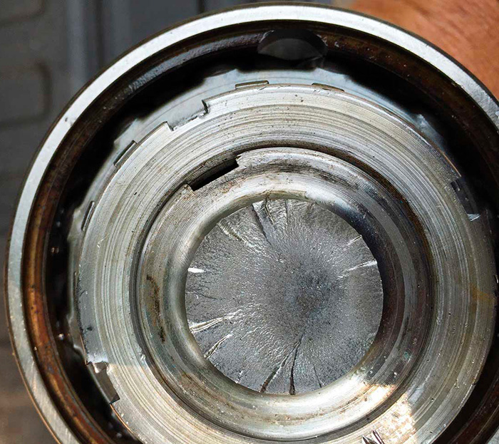 Image 1. This ANSI pump shaft was improperly loaded by a belt and sheave arrangement that resulted in rotating bending failure. Note the multiple (minimum of 15) fracture origins on the periphery. The darker area near the middle of the shaft is the instantaneous fast fracture zone. (Courtesy of the author)
Treating the Symptom
Looking at the six most commonly used pump shaft materials reveals differences in hardness, strength and corrosion resistance. One point to note is the Young’s modulus for the materials almost all fit in the same range. The Young’s modulus is in essence the material’s elasticity—how many times can you bend it before it breaks? More important is how far can you bend it on each cycle before you exceed the material’s limits?
Young’s modulus should not be confused with strength, toughness or hardness. Since the most common shaft materials all have a similar Young’s modulus, the decision to change materials is rarely the single solution to correcting the root cause of shaft failure. End users will experience higher reliability by addressing the other operational factors.
The most common cause of shaft breakage is (rotational) tensile bending fatigue. These fracture types are a result of the bending stresses previously mentioned. For a given material, the number of cycles and, to some degree, the periodicity (frequency) and the distance (strain or amplitude) of the bending cycle will determine how long the shaft will remain as one piece. The fault initiates at the weakest point, which is typically a radius, fillet or keyway. The fault may also occur at a bending moment point.
For the most common pump shaft materials, the fractures from bending stresses will occur at right angles (90 degrees) to the shaft centerline, so these failures appear almost as if the shaft snapped off or was cut off at that failure point.
A less frequent mode of failure is fatigue from torsional stresses where the fracture occurs at a 45-degree angle to the shaft centerline. Torsional failures have increased with the advent of variable speed devices.
References
Mechanical Engineering Design (5th Edition), Joseph Shigley and Charles Mischke
Machinery Failure Analysis and Troubleshooting, Fred Geitner and Heinz Bloch
How Components Fail, ASM publication, Donald Wulpi
“Understanding Factors that Cause Shaft Failures,” Pumps & Systems, June 2007, by Cyndi Nyberg, EASA
Root Cause Failure Analysis—Understanding Mechanical Failures, Neville Sachs
10 Probable Reasons That a Pump Shaft Breaks
- Operating Away from BEP: Departure from operating in the allowable region of the pump’s BEP is likely the most common cause of shaft failure. Operation away from BEP creates unbalanced hydraulic radial forces. The deflection of the shaft due to the radial forces creates a bending force that will occur twice per shaft revolution. For example, a shaft rotating at 3,550 revolutions per minute (rpm) will bend 7,100 times per minute. This bending dynamic creates a shaft tensile bending fatigue. Most shafts can handle the high number of cycles if the amplitude (strain) of the deflection is low enough.
- Bent Shaft: Bent shaft issues follow the same logic as a deflecting shaft referenced above. Purchase pumps and spare shafts from manufacturers that have high standards/specifications for shaft straightness. Due diligence would be prudent. Most tolerances for pump shafts are in the 0.001- to 0.002-inch range with the measurement as total indicator readout (TIR).
- Unbalanced Impeller or Rotor: An unbalanced impeller will create “shaft whip” while in operation. The effect is the same as if the shaft was bent and/or deflected, even though the shaft would measure straight if you stopped the pump and checked the shaft. It could be argued that balancing the impeller is just as important for slower-speed pumps as faster-speed pumps. The number of bending cycles in a given time frame is reduced, but the amplitude (strain) of displacement (due to the imbalance) remains in the same range as the higher-speed factors.
- Fluid Properties: Discussions on Newtonian versus non-Newtonian fluids will appear in a future article. Normally, the issue concerning the fluid properties involves a pump that was designed for a fluid of one (lower) viscosity but subjected to higher viscosities. An example could be as simple as the pump was selected and designed for pumping number 4 fuel oil at 95 F and later it is used to pump fuel oil at 35 F (approximated difference of 235 centipoise). Similar issues will result from an increase in specific gravity. Also note that corrosion will significantly reduce the fatigue strength of the shaft material. Shafts with higher corrosion resistance are a good choice in these environments.
- Variable Speed: Torque and speed are inversely proportional. As the pump slows down, the shaft torque increases. For example, a 100-horsepower (hp) pump at 875 rpm requires twice as much torque as a 100-hp pump at 1,750 rpm. Besides the overall shaft maximum brake horsepower (BHP) limits, users must check the allowable BHP per 100 rpm limits for the pump application.
- Misapplication: Ignoring manufacturer guidelines will lead to shaft issues. Many pump shafts have a derate factor if the pump is driven by an engine in lieu of an electric motor or steam turbine due to the intermittent versus continuous torque. If the pump is not direct drive (through a coupling) such as belt/sheave- or chain/sprocket-driven, there can be a significant shaft derating. Many self-priming trash and slurry pumps are designed to be belt-driven, so there is little issue. Pumps built for American National Standards Institute (ANSI) B73.1 specifications are not designed to be belt-driven (unless a jack-shaft is utilized). ANSI pumps may be belt- or engine-driven, but the maximum allowable horsepower is greatly reduced. Many pump manufacturers offer heavy-duty shafts as an optional extra, which can address the symptom when the root cause cannot be corrected.
- Misalignment: Misalignment between the pump and the driver even in the slightest amount contributes to the bending moments. Usually this issue manifests as failed bearings before the shaft will break.
- Vibration: Vibration from issues other than misalignment and imbalance —such as cavitation, passing vane frequency, critical speeds and harmonics — will cause stress on the shaft.
- Incorrect Fitting of Components: Another reason is incorrect mounting of impellers and couplings to the shaft (incorrect fits and clearances whether too tight or too loose). The incorrect fits may result in fretting. Fretting wear contributes to fatigue failure. Keys and/or keyways that are not properly fitted also contribute to the issue. This author prefers to hand file the key to fit the key-seat.
- Improper Speed: There are maximum pump speeds based on impeller inertia and on (peripheral) speed limits for belt drives (for example, the maximum belt speed for an ANSI pump is normally agreed to be 6,500 feet per minute). Additionally, there are cautions for low-speed operation beyond the increasing torque issue—such as the loss of hydraulic dampening effects (Lomakin Effect).