


In this month’s column, we will look at a pressurized forced main waste treatment system in an industrial process facility. A major facility expansion was completed consisting of a new research and development center and new offices for the administrative, financial, maintenance and engineering departments. In addition, the expansion affected the maintenance shop, doubling the building size.
Issues began six months after the completion of the expansion. The waste collection sumps for some of the buildings began to overflow. Each time a waste collection sump overflowed, an extensive cleanup was required, along with major operational changes to the buildings affected. There appeared to be no rhyme or reason causing a specific waste sump to overflow.
The only buildings not affected by overflowing sumps were the two new office buildings and the expanded maintenance shop.
An environmental cleanup contractor was called in to clean up the mess and to install rental sump pumps, temporary piping and storage tanks. Major operational changes were required within the affected building to prevent further overflow. The problems associated with the waste collection system caused a drop in workers’ morale, affected the operation of the entire facility and resulted in unwanted attention by the local news media.
After more than nine months of trials and false starts, the underlying cause for the overflowing sumps was identified and corrected. The problem had been the subject of many managerial meetings and changes in operational schedules, as well as additional expenses for outside engineers, consultants and clean-up contractors.
The remainder of this column describes how the problem was identified and corrected.
System Operational Group
A sketch of the waste collection system is displayed in Figure 1. The new office buildings, as well as the expanded shop, are noted on the drawing.
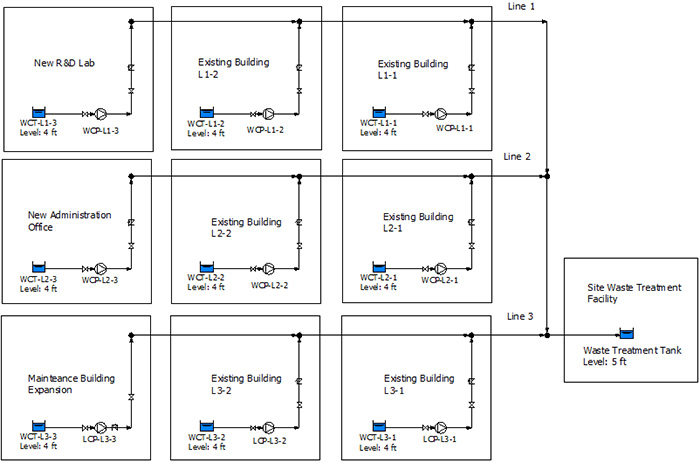 Figure 1. Waste collection system (Courtesy of the author)
Two months after the last office building was tied into the facility’s waste collection system, the collection sump in building L1-2 started overflowing. The maintenance department was contacted, and after checking out the pump and operation, nothing stood out as a problem. The supplier of the waste collection sump pump was contacted. The pump supplier reviewed the operation and checked the maintenance records to determine when the pump was serviced last. The supplier then suggested an internal inspection to check for a damaged impeller. The existing impeller was replaced and the pump was placed back in operation. The waste collection sump in building L1-2 stopped overflowing.
That same month, the waste collection sump in building L2-2 started overflowing on an intermittent basis. After repeating the initial process of pump inspection and review, it was determined that the impeller in pump L2-2 should also be inspected and replaced. The pump was then returned to service.
The problem continued to cascade and shortly thereafter the sump pumps in the existing building started overflowing. Maintenance decided to replace the impellers on all the sump pumps to hopefully correct the problem once and for all. However, this did not appear to eliminate the overflowing sumps.
The pump supplier was called in again. After reviewing the changes made to the facility’s waste collection system, the suggestion was to increase the pump head and flow to meet the increased demand. This approach would require time to determine the new pump sizing requirements, as well as time to order and install the new pumps.
Someone in the plant facility group suggested replacing the existing steel pipe with larger diameter high-density polyethylene (HDPE) pipe. The HDPE pipe would be smoother, and the larger diameter would work better with system expansion. This option could work, but the expense of digging up and replacing the piping and the resulting disruption to the plant operations appeared to be a bigger job than desired.
The plant utilities manager suggested replacing all fixed speed sump pumps with variable speed drives to meet the plant’s energy reduction goals. While this could help in meeting the company’s energy conservation goals, no one knew how it would affect the operation of the existing system.
There were many ideas and each one of them had the potential to fix the overflowing collection tanks, but no one had any idea why the system stopped working in the first place.
Simulating System Operation
A new plant engineer had experience with piping system simulation software and suggested comparing the operation of the physical piping in the plant with the simulated results. She had experience with this at her last plant and suggested the same with the waste collection system.
Using the piping flow sheet (Figure 1) and the available design information, a model was built. Figure 1 was used to establish how the various elements of the system are connected. The piping schematic identifies the equipment in the system.
Pump Elements
The manufacturer’s supplied pump curve is typically all that is needed to accurately model the pump elements. The pump head and efficiency are plotted as a function of the flow rate through the pump. The company has a specified test curve for each pump in the system, serving as the source of information.
The elevation of the pump suction and discharge are also needed to calculate pressures at the pumps.
Process Elements
The process elements consist of waste collection sumps, the pipeline details and the facility’s waste treatment tank. The individual waste collection sumps provide the inlet system boundary.
The information needed on each sump includes the tank’s base elevation and operating level. Other information can include the normal inflow along with the inflow into the tank and its dimensions.
The information needed for the pipelines includes the pipe length, diameter and corresponding pipe roughness.
The type and number of valves and fittings in the pipeline will also affect the minor losses associated with these devices.
Control Elements
The system is controlled by the level in each tank. The waste collection pump is started on a high-level control, and the pump is stopped on a low-tank level.
System Operation
Additional system operating information is needed for an accurate simulation. We must know the properties of the process fluid, specifically its fluid type and temperature. Since the fluid in the waste collection system is predominantly water, that information is easily available.
The flow rate through the pump is based on the level in the waste collection sump, along with the pump’s outlet pressure.
For example, when pumping from a tank, the flow rate through the pump decreases as the tank is pumped down. As additional pumps are started in the system, the pressure in the discharge header increases, causing the flow rate in each individual pump to decrease.
Using the Simulation Results
Once the model is completed with the above information, the simulation software will calculate the operation of the entire piping system. Since the system operation is based on a level control and the tank levels and pumps affect each other, we will model the system showing the interaction over a period of time.
When comparing the actual system operation with the model, the results provide insight about why the waste collection tanks overflow.
While running the model, it was discovered that when a pump in any of the new buildings switched on, a significant decrease in the flow rates from the existing collection sumps resulted.
Under conditions with more than three existing pumps in operation at any given time, starting a pump in the new buildings caused the flow rate from the tank to be less that the flow rate into the existing tanks, causing the overflow.
In looking at the design point supplied to the pump manufacturer, it appeared that the head required was overstated, and the pump supplier selected a pump that caused the sump pump to pump down too quickly.
Another result of the simulation was the design flow rate into the sumps of the existing building was greater than that called out in the pump specification.
Over time, the flow rate into the existing building waste collection sumps increased, resulting in a longer time to run the waste collection pumps. Some of the increase in flow rate was due to greater waste generation load from the building and some was of it was due to leaking water into the system.
Using the system simulation results along with the operation of the actual piping system, plant management was able to discover the system problems and look at ways to improve the system to meet actual system conditions.