


When navigating the Las Vegas Strip, one can’t help but be impressed by the array of water features, waterfalls and fountains. At the heart of each are the pumps that drive them. Proper pump application and reliability are paramount to maintaining these attractions.
One such water feature, an indoor casino waterfall using eight pumps regulated to produce the desired fall effects, is the subject of this article. This indoor water feature provides the backdrop for an exclusive luxury bar and lounge. However, running all eight pumps resulted in excessive failure rates, compromising the feature and diminishing the site’s appeal.
The system uses horizontal overhung pumps, each driven by a variable frequency electric motor (see Image 1). The pumps are constructed of cast iron and, with the exception of impeller diameters, identical.
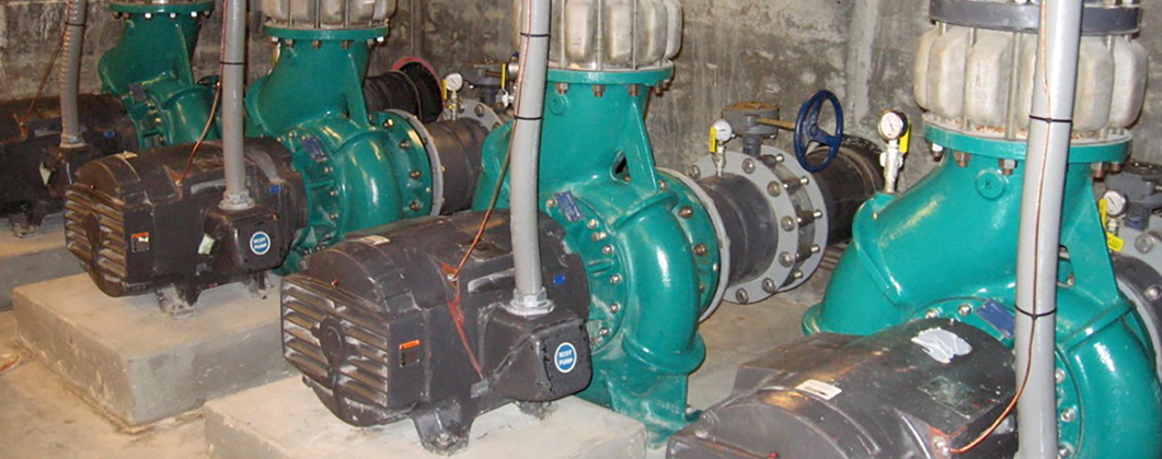 Image 1. Cast iron horizontal overhung pumps that drive the waterfall. (Images and graphics courtesy of ProPump Services)
The mean time between repair (MTBR) had become unacceptable at one-month intervals. Seal failures were typical casualties, but significant impeller and casing cavitation damage was also becoming apparent. To identify the problems, a comprehensive hydraulic and mechanical assessment was commissioned to determine the status of the pumps and provide recommendations encompassing materials, maintenance and operations.
Pump & System Assessment
Instrumentation was installed, and each pump was tested under typical operating conditions. Casino patrons visit the feature more frequently during the evening, which provided an opportunity earlier in the day to assess the system in configurations that included pump pairings and speed regulation. The following operating parameters were measured:
- discharge flow
- suction and discharge pressures and temperatures
- pump speeds
- vibration signatures
- net positive suction head available (NPSHA)
The measured data was compared to the manufacturer’s curves. Also, a system resistance curve was generated from site data. The as-found performance for all eight is averaged in Figure 1.
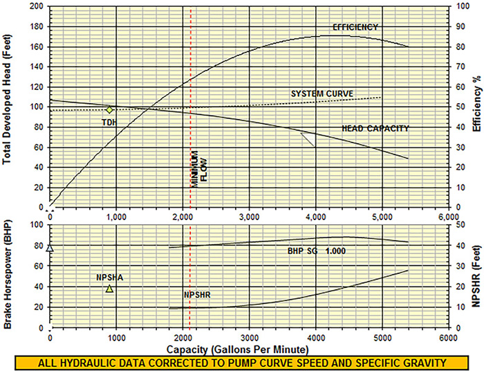 Figure 1. Typical hydraulic performance
 The total developed head (TDH) of all the pumps was approximately 5 percent below expected at the measured flows. The desired water feature esthetic required all eight pumps to operate at 22 percent of the best efficiency point (BEP) capacity and significantly below the manufacturer’s recommended minimum continuous stable flow (MCSF) of 2,050 gpm. The NPSHA was determined at the measured flow rate. However, the net positive suction head required (NPSHR) curve did not extend to the measured field. This was concerning since NPSHR increases at low flow rates for some designs.
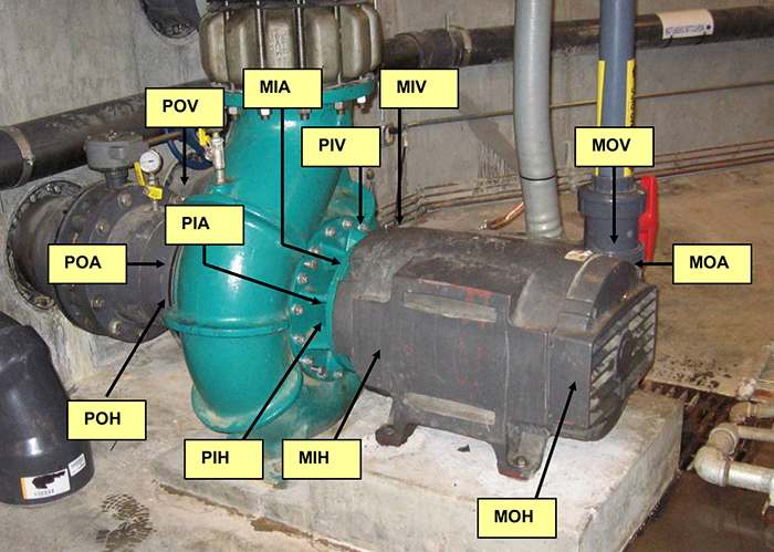 Image 2. Typical vibration data point identification
Concurrent with the hydraulic data acquisition, vibration signatures were recorded at the locations indicated in Image 2. The unfiltered amplitudes are presented in Figure 2.
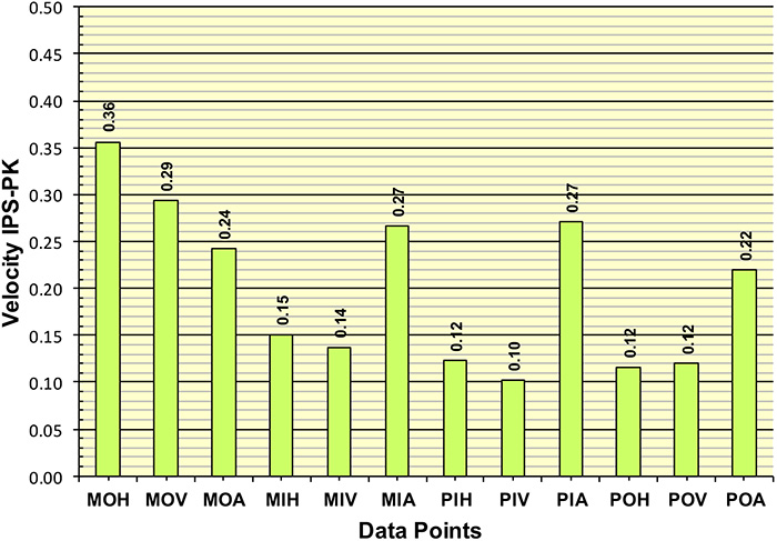 Figure 2. Unfiltered vibration amplitudes
The amplitudes were higher than expected for pumps of this type. A review of the associated spectra provided further insight. The spectrum and time waveform presented in Figure 3 is typical of the majority of the signatures collected from all of the pumps. Note the spectrum is replete with random frequencies commonly referred to as spectral floor noise, which is indicative of hydraulic anomalies such as recirculation or cavitation. Further evidence of these anomalies is presented in the associated time waveform where random impacting is evident, a typical energy signature associated with cavitation. Additionally, during the low flow testing, audible noise associated with extreme cavitation was present.
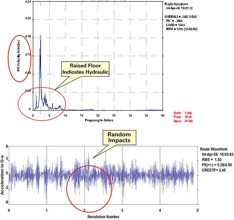 Figure 3. Spectrum and time waveform typical of the signatures collected from the pumps
System Resistance Curve
Centrifugal pumps always operate at the intersection of the pump head capacity and the system resistance curves. The pump head capacity curve is supplied by the manufacturer while the system curve is a plot of the head requirements as a function of flow, calculated by the system designer.
System resistance curves include three components:
- static head (elevation)
- pressure head (pressurized vessel)
- friction (including entrance and exit head losses)
Friction losses are primarily a function of pipe and component liquid velocity. When developing the system curve, only the friction losses change with flow rate. For the subject pumps, the system curve was comprised of static elevation and friction losses only. Since pipe diameters were sized for relatively low velocities, the system curve was a primarily static head with minimal friction contribution.
The minimal slope (flatness) of the system curve and the pump curve allowed a large decrease (or increase) in flow rate for a minor change in pump speed; therefore, the waterfall flow rates could be altered with small variations in pump speed.
Minimum Flow Defined
Pump minimum flow can be defined in two ways: thermal and mechanical. Thermal minimum flow is that flow rate (for a given speed) required to avoid flashing or vaporization within the pump. Mechanical minimum flow is the flow required to avoid mechanical damage as a result of off-design (low flow) operation. Pump manufacturers typically publish the mechanical value, also referred to as MCSF. For the subject pumps, the MCSF was documented as 2,500 gallons per minute (gpm) at 1,750 rotations per minute (rpm). For the test data plotted, the MCSF was adjusted for pump speed. Note that all pumps were operating well below the MCSF.
NPSHA/NPSHR/Submergence
NPSHA is the total suction head in feet of liquid above the liquid vapor pressure. NPSHR, determined by the pump manufacturer, is a function of many factors such as impeller eye design, flow rate and shaft speed. For all operating conditions, the NPSHA must exceed the NPSHR.
Submergence is the minimum intake/suction piping depth required to prevent vortices and excessive flow pre-whirl. For the subject installations, the NPSHA was determined to be adequate, and no indications of vortexing were observed.
Cavitation & Suction Recirculation
Cavitation bubbles form when the pressure of the pumpage falls below its vapor pressure. The cavitation bubbles are swept through the impeller and casing to a regime of higher pressure where the bubbles implode.
The energy release manifests as noise described as popping. The energy release of the collapsing cavitation bubbles are of such magnitude to cause significant damage to the pump components. Over time, as the integrity of the pump’s components become compromised, seals and bearings are subject to premature failure.
Suction recirculation cavitation can occur during pump operation at reduced flow rates when secondary flows form in the eye of the impeller. In addition, flow separation can occur when the incidence angle or the difference between the angle of the flow and pump vane inlet angle is beyond a critical value. The secondary flows can actually reverse flow out of the impeller eye with the bubbles collapsing upstream of the impeller.
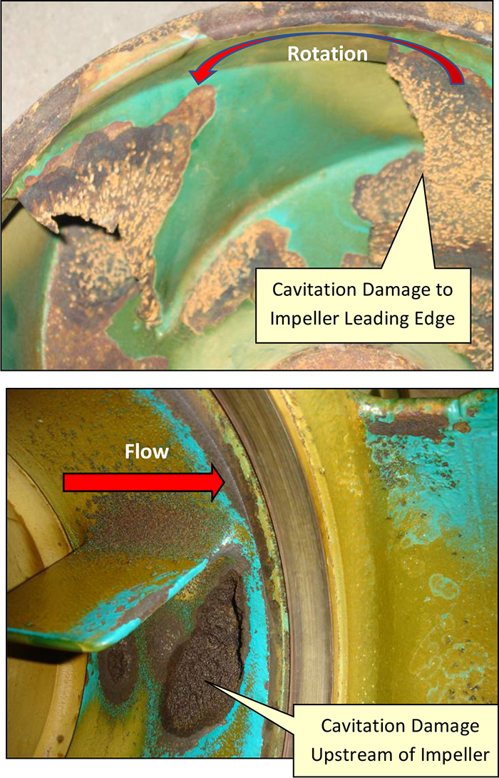 Image 3. Impeller damage and casing damage due to cavitation
 Pump disassembly and inspections revealed significant damage to both the impeller and casing after runs of less than one month after repair. As shown in Image 3, the cast iron impeller inlet tips were compromised with substantial material removal. Similarly, the casing inlet adjacent to the baffle revealed extensive material degradation, compromising casing wall thickness constituting a safety hazard.
Suction Specific Speed (Nss)
Nss is an index of hydraulic design describing the suction capabilities and impeller characteristics. Impeller designs with an Nss above about 8,500 are particularly sensitive to operation at low flow rates. The subject pumps have a Nss of 11,341, making them more susceptible to suction recirculation and cavitation at low flow rates. The damage is exacerbated during cold water operation, which is 50 to 60 F at this installation.
Suction Piping
The suction inlet design was not ideal. It featured a horizontal pipe with the ends capped and a series of slots on the bottom parallel to the centerline. Opposite the slots (180 degrees) on top of the pipe was a series of holes for venting air. The end user advised that the suction runs are typical for the water features industry and the area of the inlet slots is sufficient to maintain velocities within guidelines.
All of the installations featured a butterfly valve close to the pump suction with several having elbows and reducers installed upstream of the valve. A straight run of six pipe diameters is typically recommended for pump suction piping, but was not present at this installation.
Experimentation
A review of the operating protocols and test data made it apparent that not only were too many pumps operated, but they were significantly oversized for the application.
The use of eight pumps for the waterfall was excessive, resulting in wasted energy and the observed internal damage. This was proven by pairing the pumps and running only one pair at a time, adjusting speeds as required to maintain the desired aesthetic appearance. The final result was two pumps running near rated speed. Not surprisingly, the cavitation noise was eliminated, and associated vibratory amplitudes were significantly reduced. After several months of operating with the new operating protocols, the two running pairs were disassembled and inspected with no damage or wear noted.
Conclusions & Recommendations
The current pumps were oversized for the application, compromising pump life and consuming excessive power. Smaller pumps, better sized to system requirements, were recommended. To increase pump longevity, replacing the original impellers and casings with 12 percent chrome was recommended. Both CA-15 and CA6NM are suitable and would increase cavitation resistance by a factor of five. Observed damage to the pump casings compromised pressure boundary integrity. As the cast iron casing material is not readily weld-repairable, investigating a casing repair by installing a 316L stainless sleeve in the suction nozzle was recommended as an alternative to casing replacement. Pump longevity and power savings were best realized by operating as few pumps as possible. Testing revealed that single pump operation provided sufficient flow, although system modifications, such as the addition of baffling, would be required.
Changing a Culture
The root cause of the deteriorating MTBR was predictable, operating too many oversized pumps for the required service, but the testing had to be conducted to explain how the operating methods were causing the observed damage and the deleterious effects on the MTBR.
It is up to facility operators to accommodate artists and designers while optimizing the machinery operation. It took hours of experimentation with different pump pairings and speed balancing to convince skeptical operators that they could provide the required water feature aesthetics with energy and maintenance savings, ultimately convincing them that less is more.