


Efficiency degradation in pumps can be related to three areas. Worn clearances between the wear rings of the impeller and the casing can increase leakage and drop the volumetric efficiency of the pump. Rough, rusty and damaged internals increase friction, reducing hydraulic efficiency. Finally, rubs, galling, friction in the mechanical seals and bearings, can result in the reduction of mechanical efficiency.
Together, these three pumping problems reduce the available flow, lower pressure and/or require more power consumption. These three issues also make a pump less reliable. Pump efficiency and reliability are often intertwined.
Centrifugal Pump Reliability Problems
Consider, for example, a case of reliability problems in a multistage, horizontally-split centrifugal pump in service at a pipeline booster station. This pump had been de-staged from the original, four-stage opposite impeller design, to a three-stage modification. Originally, the pump service was for lower flow and pressure. To match a new set of operating conditions (3,100 barrels of gasoline per hour, at 690-psi pump developed pressure) the first stage of this pump was replaced with a blank pass-through spool.
In the case described above, the pump rotor seized, on average, nearly once per year, resulting in poor reliability, increased repair costs and lost production. Upon inspection, a low suction pressure zone was found, which resulted in periodic flashing of the product, causing cavitation, which affected the side of the bushing adjacent to this low pressure zone, as evidenced by the pitting that was found on the rotor and bushing area. Flashing of product in that area resulted in a loss of the needed lubricating film of liquid within the clearance of the bushing. This lack of lubrication liquid also contributed to the rotor seizure at the bushing area.
Figure 1 illustrates the flow of product through the pump, indicating pressure increase from one stage to another, as well as showing the orientation of the internal bushings with their clearance separating internal regions of pressure from each others.
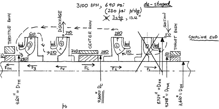
Figure 1. Product flow through the pump
Four main types of clearances are:
• Throat bushing, which separates the suction (inlet) pressure (50 psig) from the mechanical seal cavity (to the right of the illustration, not shown in Figure 1). Since the seal area is immediately adjacent to the suction area, it is under the same pressure as suction.
• Center bushing, which separates the intermediate-pressure from the high-pressure zones. This pressure differential has increased due to the de-staging, making this a more important leakage path.
• Throttle bushing, which separates the intermediate pressure from the suction pressure (the area to the left of the illustration, past the throttle bushing, is connected to the suction area via a balance line).
• Impeller-to-case wear rings. Typically, there is one stage pressure across these rings.
• Hub wear rings. Typically a minimum flow area with little differential pressure. This pump has only one such clearance between stages 3 and 4.
In trying to solve the reliability problem, the designer or engineer needs to balance the conflicting requirements of efficiency and reliability. With a power level nearly 2,000 hp, each percentage point of efficiency savings translates to approximately $13,000 per year, assuming non-stop operation, at 10 cents energy cost of each kilowatt-hour. Efficiency is a key criteria for these large high energy pumps.
We try to solve the reliability while keeping the clearances as close as possible to reduce leakage (effect on volumetric efficiency), but not so tight that contact occurs the the high speed (3600 RPM): rotating parts would gall and seize to the stationary parts (the casing and impeller wear rings).
The Solution
The answer to the problem was applying a graphite/metal alloy, to allow the reduction of clearances (this material is non-galling). As a non-galling material clearances can be cut to half the normal API clearances for metal fitted pumps. This change improved reliability as well as saving energy. Initially, only the throttle bushing, the most critical part, was made from Graphalloy to replace the originally supplied metal part. The clearance was reduced from 0.014 in. to 0.008 in., which resulted in efficiency improvements of approximately 2.2 percent. This improvement resulted in nearly $30,000 in yearly energy savings. At the same time—due to the non-galling qualities of the new material, an occasional rotor contact was not a problem, and rotor seizures were eliminated, making this pump much more reliable, and production uptime was improved.
References and Bibliography
1. Nelik, L., “How Much Energy is Wasted When Wear Rings Are Worn to Double Their Initial Value?,” Pumps & Systems, March 2007, page 18
2. Knoch, H., Kracker, J., and Long., W., “Sintered Alpha Silicon Carbide Pump Bearings – Tribological Materials Optimization to Improve Reliability,” Texas A&M Pump Symposium, October 1993, Houston, Texas.
3. Komin, Robert P., “Improving Pump Reliability in light Hydrocarbon and Condensate Service With Graphite/Metal Alloy Wear Parts” Texas A&M Pump Symposium, 1990, Houston, Texas.
4. Walker, Eben T., “Bearings Take the Heat,” Machine Design, May 2004.
5. Komin, Robert P., “Improving boiler feedwater pump reliability with Graphite/Metal alloy wear parts,” Pump Engineer, May 2004.
6. “GRAPHALLOY Pump Application Guide,” Graphite Metallizing Corp., USA, copyright 2008.