


I received many comments and suggestions on proper installation practices, following my article “Grouting: Pumps and Telephone Poles,” Pumps & Systems, July 2010). My long-time friend and colleague, Luis Rizo, discussed these comments and wanted to share with the readers some additional recommendations and ideas on the subject.
Question
How is the width and length of a shim determined for leveling machinery during alignment or installation? Are there general rule-of-thumb practices? We have a recycle gas Ingersoll-Rand barrel compressor powered by an Electric-Machinery 1,500-horsepower/2,300-Volt motor with a 3420-S frame. The motor rests on two continuous 60-inch long by 6-inch wide sole plates. The two motor feet measure 59 inches by 5 inches each. What is the potential damage to alignment and/or the motor by using small (6-inch by 6-inch) shims versus large (24-inch by 6-inch) or continuous (60=inch by 6-inch) shims?
Jerry Choate
Murphy Oil USA, Inc.
Superior, Wisc.
The Answer
Luis Rizo offers this advice:
The question you should focus on is– “How do I create a monolith that will absorb all the force to the base and foundation of the equipment?” The unbalanced force of a reciprocating compressor is proportional to the reactive force. In a liquid slug scenario as you probably know, this force is not measurable, so it amounts to an infinite amount of force.
I would try to get a shim as large as practical to cover the width of the foot for the hold down bolt at each of the feet. Another option is to use a liquid chock to level and hold your machine down, so that the complete structure becomes a monolith. Figure 1 is a similar compressor, grouted many years ago, that it is still operational today at the Exxon Baytown refinery/chemical plant complex.
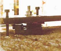
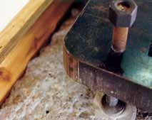
Figure 1. A compressor, grouted many years back, that it is still operational at the Exxon Baytown refinery/chemical plant
On www.pump-zone.com, see the figure with some ideas on leveling techniques for horizontal baseplates. There are four methods to provide vertical adjustments to a horizontal baseplate. A single wedge, parallel wedges, shim packs and jacking screws on metal plates. The preferred method of the author is the jacking screw on metal plates combined with metal shim plates. The following drawings illustrate the four methods.
Julien Le Bleu adds:
The first question is generally to try to size the shims to match the feet if possible. When I was with GE, we often had large sole plates. We would make several, non-shrink grout pads along the length of the plate and the same width as the plate. This was done after the plate was leveled with jacking screws and checked for no humping or sagging. The small pads were made with Styrofoam and liquid non-shrink grout poured in and allowed to set up.
The plate was then pulled and the foam form was removed. The grout was cleaned and the plate set down again. If all is correct, make another form around the entire plate and pour non-shrink grout into it and have it include the small pads poured previously.
If the plates need to be shimmed up to get to elevation do it with stainless steel shims on each of the small pads. When all is as you need it, then complete the step above, and put it all in the final pour of non-shrink grout.

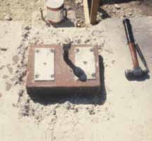
Figure 3. Positioning of plates for jacking screws near the anchor bolts
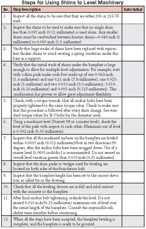
Steps for Using Shims to Level Machinery
Pumps & Systems, November 2011