


Q. What is a dynamic seal in centrifugal pumps?
A. A dynamic seal is one that only operates when the pump shaft is rotating and has no seal effect when the shaft is stationary. It consists of an expeller or set of expellers located in a separate chamber behind the impeller, which is typically fitted with expelling vanes on the back shroud.
When the pump is running, the centrifugal seal generates pressure Pe to equalize the pressure Pb, as shown in Figure 12.3.8.3.6, so that the pump operates without leakage.
A centrifugal (dynamic) seal needs to be combined with a backup or static seal to prevent leakage when the pump is not running. The backup sealing device must seal statically when the pump is shut down, and it must run dry during pump operation.” This can be accomplished by dry-type packing, multiple lip seals, other proprietary devices or mechanical seals with either dry run capabilities or fitted with a separate flush.
There is a maximum allowable suction pressure (Ps) which, depending on the speed of rotation, a dynamic seal will not operate properly. For this reason, centrifugal seals are not effective on the second or higher stages of multiple pump installations—configurations in which the pumps are arranged to have the full discharge of the preceding stage applied to the suction of the following stage.
If the pumps are installed at specified intervals and elevations spread along a slurry transport line, then it is possible to use dynamic seals on all stages. The arrangement should be such that the suction pressures on each stage are approximately equal and do not exceed 10 to 20 percent of the discharge pressure. An analysis should be made of the centrifugal seal performance, based on actual head, flow and suction pressure, so that proper operation is ensured
Additional information about dynamic seals is available in HI Standard ANSI/HI 12.1-12.6, Rotodynamic (Centrifugal) Slurry Pumps for Nomenclature, Definitions, Applications, and Operation.

Figure12.3.8.3.6. Pressure Pe equalizes the pressure Pb.
Q. How important is shaft deflection in rotodynamic (centrifugal) pumps, and how is it determined?
A. Shaft deflection is a design criterion that greatly influences pump performance due to its effect on the mechanical seal, internal clearances and bearings.
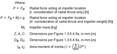
Radial loads acting on the rotating impeller(s) are transmitted directly to the pump shaft. This force will deflect the shaft where it is applied, irrespective of the bearing configuration. The direction of the hydraulic radial load, at a given operating point, remains constant with respect to the pump casing. However, it is seen as cyclic stress reversal with respect to the rotating shaft and has a dynamic effect on the mechanical seal. The shaft must be designed to accommodate this hydraulic radial load in conjunction with the additional radial load imposed due to the mass of the impeller(s) and other rotating components. Under these conditions, the rotor must be stiff enough to limit the resulting deflection within parameters predetermined by internal clearances and mechanical seal requirements.
Dynamic deflection of the pump shaft changes the relative location of the mechanical seal faces and, therefore, has a large impact on the overall seal life. For a mechanical seal to reach its designed lifetime, several requirements have to be met. From a static or dimensional point of view, the relative locations of the primary, stationary and rotating faces must be held within control limits. These limits can be met by using a combination of flexibility within the seal assembly and the appropriate manufacturing procedures and processes.
Limiting shaft deflection will also improve the packing life when a packed stuffing box is used as the method of shaft sealing. Internal operating clearances are also governed by the anticipated dynamic shaft deflection. Adequate clearance must be verified at critical locations by using the shaft deflection equations.
Shaft deflection has an effect on pump bearing life because shaft deflection directly affects the angular misalignment between the inner and outer bearing rings. External loads such as coupling misalignment should also be considered. If hydraulic radial load test data are not available, hydraulic radial loads can be calculated in accordance with Section 1.3.5.1, calculation of radial thrust for volute pumps.

Figure 1.3.5.4.2.4a. Overhung impeller
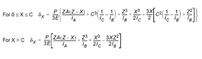
Refer to HI Standard ANSI/HI 1.3, Rotodynamic (Centrifugal) Pumps for Design and Application for additional ways to estimate the shaft deflection of pumps.
Q. When purchasing vertical turbine pumps, can the motors be purchased directly from a motor supplier?
A. Vertical turbine pump motors are normally supplied with a registered (rabbet) fit mounting base conforming to industry standard dimensions and drilling. It is customary for the vertical pump manufacturer to supply the motor to ensure proper mating of the base flanges, proper coupling of the shaft extensions, specification of the axial thrust requirements and specification of the start-up torque requirements.
Alignment of the motor shaft to the pump shaft can be affected by the motor base register eccentricity and the mounting base face runout. Care must be exercised in the procurement of the motor to ensure all motor-to-pump interface requirements are met. Usually, the purchaser's contract documents assign responsibility for procurement of the motor to the pump manufacturer to ensure that the design interface issues are covered. This is particularly important when a variable speed drive (VSD) is included in the package.
The National Electrical Manufacturers Association's (NEMA) Standard MG-1 and the International Electrotechnical Commission's (IEC) Standard 72-1 define motor base mating dimensions for vertical pump motors.
Pumps & Systems, February 2011
Click here to see a Readers Response to this article.