


Editor's Note: This is the last in a six-part series on dry gas seals. For other articles in this series, click here
Last of Six Parts
The final factor influencing the reliability of a dry gas seal is the most critical—ensuring proper quality and providing sufficient flow of seal gas to the dry gas seal at all times. To do this, assess the application to identify the need for additional equipment to provide sufficient, clean, dry and quality seal gas for every dry gas seal. To condition seal gas, a cooler, heater, pre-filters/liquid knockout, heat trace, insulation or booster might be required. End users may need none of these items, one item, a combination of them, or all of them to provide the right quality and flow of gas.
In optimal situations, the equipment required for the conditioning system will be identified when the seal and seal supply are selected. The seal configuration, seal gas source and seal gas have major influences on what a conditioning system includes.
Seal Gas Boosters
The first decision to make when selecting equipment for a conditioning system is the ability to flow clean seal gas to the seals at all times. If the source of the seal gas is from the compressor’s discharge, sufficient seal gas is only supplied when sufficient differential pressure across the compressor exists.
In startup, shutdown, standstill or recycle conditions, there is not always sufficient differential pressure available to provide flow to the dry gas seals. This allows unfiltered gas to enter the seal cavity and reduce the seals’ reliability. For those conditions when seal gas flow may be low or lost, a high-pressure header or alternate source could be an option.
This is an ideal way to ensure seal supply gas flow, as long as the compressor does not have to be completely isolated (the valves on the inlet and outlet of the compressor closed).
If the compressor is isolated, the pressure from the seal supply gas builds up in the compressor and seal gas flow is quickly lost. If using a high-pressure header or alternate source, this is not a good solution for maintaining flow. The gas must be vented to atmosphere to prevent pressure buildup in the compressor. A good solution is to leave the suction unit valve or a bypass valve open, allowing the added gas to flow back into the suction supply. The ideal solution for most applications is to use a booster (see Image 1) to maintain the seal gas flow.
 |
| Image 1. Seal gas boosters ensure that seal gas flow is provided at all times. |
With a booster, the gas in the compressor is used. No gas is added to the system. The booster draws the gas out of the compressor, through the filter, pushes it into the seal cavity and back into the compressor. This ensures that clean seal gas is provided to the dry gas seals when the differential pressure across the compressor is not present.
When selecting a booster, many different options are available from compressor original equipment manufacturers (OEMs) and seal manufacturers. Electric-driven boosters are the most reliable. They are centrifugal and have fewer moving parts, which reduces wear components and increases reliability. They can operate continuously for long periods without worry of booster failure. When the compressor is pressurized, started or shut down, or seal gas flow becomes lower than acceptable, the compressor logic will power the booster and open a valve to flow seal gas through the booster.
The booster then takes over the job of producing seal gas flow to ensure clean seal gas to the seals. Once sufficient or excessive flow is produced due to the compressor starting or the compressor recycle valve closing, the booster is turned off the valve to the booster closed. The seal gas then flows through the system based on the differential pressure across the compressor. A seal gas system with a booster ensures that seal gas is supplied to the seals whenever gas is present in the compressor.
Seal Gas Conditioning
Now that the dry gas seal is receiving seal gas when required, other concerns must be addressed. The gas quality is also important. A dry gas seal system’s standard filters only remove small amounts of aerosols. They cannot remove liquid droplets or large quantities of contamination in the gas stream. If large quantities of liquid or particulates are present in the seal gas, additional filtration is required.
Natural gas pipelines are typical applications in which only a pre-filter to handle coarse liquids and particle contamination may be required. Selecting an effective and reliable pre-filter is essential for proper operation. Some pre-filters use mist pads to manage liquids. The efficiency of mist pads depends on the correct velocity of gas as it flows through the mist pad. A cyclone (see Figure 1) is a better option for effectively removing larger particles and liquids from a gas stream.
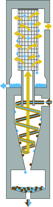 |
Figure 1. Cyclones are an effective
way to remove coarse liquids and particulates
Several cyclone models have been developed specifically for seal gas applications. They have a much wider range of operating velocities for removing particles and liquids. A reliable dry gas seal system should use a pre-filter that includes a cyclone.
Not all natural gas pipelines can manage with only a pre-filter. Additional conditioning may be required depending on the gas composition. Gas can become liquid when its pressure and temperature decreases. During normal operation, when compressor discharge gas is used for seal gas, the pressure of the gas decreases from discharge pressure to atmospheric pressure through control valves, orifices and the dry gas seal. As the seal gas flows through the system, it will also decrease in temperature. The temperature decrease of the gas is a result of cold pipes exposed to atmospheric temperatures.
The gas temperature also changes due to the Joules Thompson effect—when gas expands (gas pressure decreases) the temperature of the gas changes. For most gases, this will cause a decrease in temperature as the pressure decreases, since the gas expands when gas flows through the control valves, orifices and the dry gas seal. The decrease in gas pressure and temperature can cause components in the seal gas to become liquids.
The challenge is that different gases will become liquid at different temperatures and pressures. Typical gases are composed of more than one gas, so the total gas composition must be analyzed to identify at what pressure and temperature liquids will form. Any liquid that flows or forms between the dry gas seal faces is harmful to the seal. The gas film becomes unstable, causes contact between the seal faces and generates heat. The instability and heat will eventually cause a seal failure.
Dew-Point Analysis
To determine if liquid forms in the seal gas, a dew-point analysis must be completed for the gas composition (see Figure 2). For an accurate dew-point analysis, a precise gas composition must be provided. Frequently, gas compositions are produced by identifying gas components with C values no greater than C6. Higher C components are lumped together or left out.
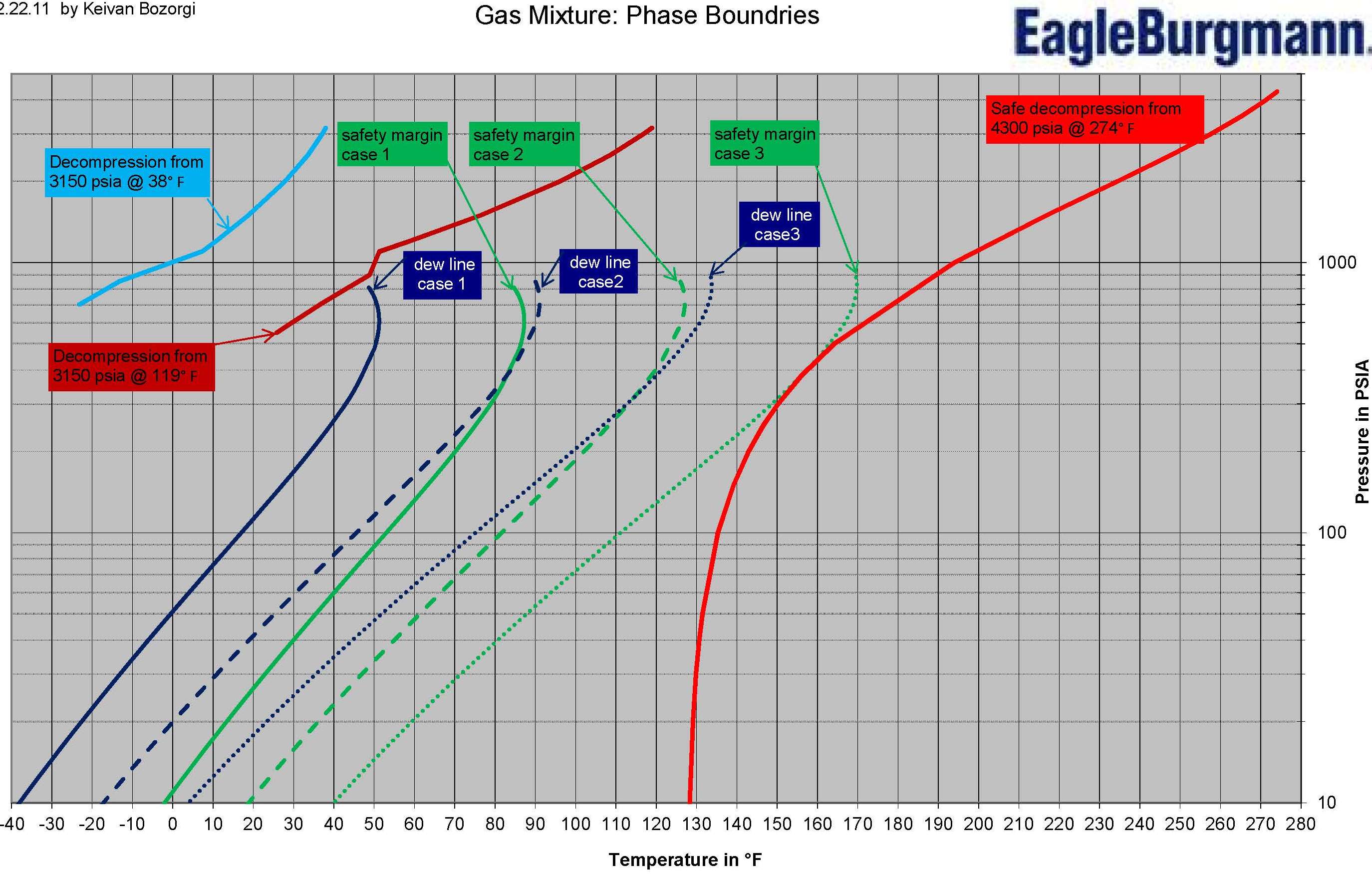 |
| Figure 2. Accurate dew-point analysis provides the information for identifying the required gas seal conditioning components. |
Water is sometimes removed before the gas analysis is completed. Prior to identifying a gas composition, gas samples are dried to remove wet contaminants from the gas. The drying procedure, however, will produce an inaccurate gas composition. To produce an accurate gas composition, do not dry the gas sample. An un-dried gas sample will ensure that components up to C20 and water are identified and shown as a percentage or parts per million present in the gas.
This provides an accurate dew-point curve, allowing for the identification of the required seal gas conditioning equipment needed to remove or manage the liquids in the gas and prevent unexpected seal failures.
From a dew-point analysis, a phase envelope for the gas is established. This will indicate the pressure and temperature at which dual-phase gas is produced (gas with liquid mist or droplets) and when the gas will become a total liquid. The next step is to plot a line/curve on the graph to show how the temperature of the gas decreases as the pressure decreases. This is plotted from the discharge pressure and temperature to the atmospheric pressure.
The gas temperature will decrease when passing through the control valves, orifices and seal faces, producing a curve in the line as the pressure decreases. The plotted line provides an indication of the temperature and pressure of the seal gas in relation to the dew-point line. Gas that maintains a temperature of at least 20 Kelvin (K) away from the dew-point line has sufficient margin to ensure that no liquids will form.
This analysis identifies that seal gas conditioning is not required during normal operation, but other operating conditions must be considered. When the compressor is cold and at ambient temperature, a different curve is produced. This condition must be analyzed, as well.
Therefore, it is also imperative to produce a curve depicting pressure and temperature drop for the seal gas at ambient conditions. Typically, this is a settle-out pressure, which is at a lower pressure than discharge. The plotted line is slightly different compared to the one produced for the discharge pressure because the Joules Thompson effect has less influence at the lower pressure. Any other conditions where the seal gas decreases from a high pressure to atmospheric pressure is considered to ensure that 20 K is maintained from the dew-point line at all times. Where sufficient margin from the dew-point line is not maintained, seal gas conditioning is required.
Maintaining a sufficient dew-point margin is required through all operating conditions. The most challenging conditions may not be when the compressor is operating, but when it is in standstill conditions. If standstill conditions are not considered and liquids form in the seal gas, a failure can occur at startup or after a short period of compressor operation. Any alternate gases or “off” conditions of the process gas should be considered as well to ensure that the dew-point margin is maintained and to make certain that the right quality of gas is always provided.
When the dew-point analysis has been completed, determining what additional equipment is required is important. If all operating conditions maintain the 20-K margin from the dew point, then no additional equipment is needed. When a 20-K margin is not maintained, then a heater is needed to establish a sufficient dew-point margin. To assist in maintaining a sufficient dew-point margin and reducing the size of heater required, a pre-filter is included when a heater is used.
For this type of conditioning, the gas is allowed to cool as it flows through pipes from the compressor discharge to the pre-filter. As the gas cools, the pre-filter strips out any liquids in the gas. Once the seal gas leaves the pre-filter, the line should be heat traced and insulated to ensure that no further liquids form in the seal gas and that the seal gas temperature is maintained.
The seal gas then goes into the heater, where it is heated to maintain the 20-K margin from the dew-point line. After heating, the seal gas piping is also heat traced and insulated from the heater to the compressor to help minimize temperature loss. Ideally, a temperature transmitter controlling the heater should be placed at the compressor to ensure that the temperature is maintained as it flows through the line from the heater to the compressor.
In some cases, the gas dew point is at a higher temperature than the suction temperature of the compressor. When these conditions occur, even with a liquid knockout and heater, the seal gas temperature cannot maintain sufficient margin from the dew point. For these cases, the gas temperature must be dropped below suction temperature, or lower, prior to the liquid knockout. Dropping the temperature of the gas moves the gas across the dew line into the dual phase, where both liquids and gases are present in the seal gas. The liquids in the gas are then removed by the liquid knockout/cyclone.
With the liquids removed, the gas composition changes, which changes the gas dew point. The result is a dew point below the compressor suction temperature and the ability to maintain a 20-K margin is achieved, preventing liquids from forming in the seal gas as it passes through the seal. Typically, lowering seal gas temperature is performed with a fin fan cooler or a tube-and-shell cooler. Lowering the dew point reduces the temperature increase that is required for the seal gas if components of the gas are removed.To summarize, an effective conditioning system will ensure that quality seal gas is provided to the seal at all times. To guarantee an effective conditioning system, follow these steps:
- Evaluate using an alternate source or booster to provide adequate seal gas flow during transient conditions.
- Assess the liquids and particles in the seal gas to verify what level of filtration is required.
- Collect an accurate seal gas composition.
- Analyze the gas to identify if liquids will form in the gas as it flows through the dry gas seal system.
- Ensure that the correct equipment is supplied by the OEM.
Dry Gas Seal Reliability
Summarizing the six articles presented in this series, the reliability of dry gas seals is not entirely based on the dry gas seal. Dry gas seal reliability is influenced by:
- Knowing the components required for a reliable dry gas seal system
- Selecting the proper seal for the application
- Choosing the best design features in the dry gas seal
- Using the proper type of separation seal and process seal for the application
- Effective dry gas seal panel design
- Choosing the correct components for seal gas conditioning
To ensure that the dry gas seal system delivers the highest reliability achievable from the dry gas seal, consider all six factors. Not only will the correct seal and panel provide reliability with a minimum of six years mean time between repairs (MTBR), it also reduces utility, maintenance and repair costs. Always ensure that the seal vendor is included in the design of the total dry gas seal system to guarantee expected reliability.