


Many times, valve problems are not a function of the valve at all, but stem from problems with the piping system design, valve location, poor installation practices or selecting the wrong valve for the application.
The following information is a guideline of valve basics.
Piping Design: 3 Basic Rules
Rule No. 1: All valves work best when installed in a nonturbulent flow condition.
Strive for smooth, nonturbulent flow in all design cases. Five times the NPS (nominal pipe size—outside diameter [OD] of a pipe) of straight pipe both upstream and down is recommended, but some valve designs can be installed with less straight pipe than that. Acceptability of nonlinear piping is case specific. It is always a good idea to consult the valve manufacturer; they will be able to give guidance to avoid future maintenance problems.
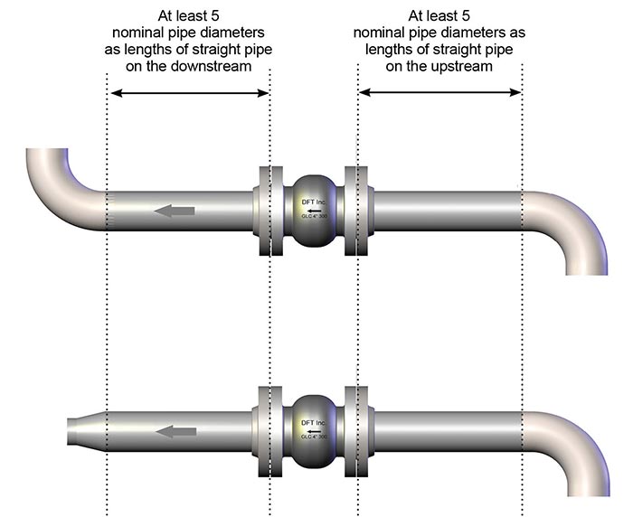 Image 1. Suggested check valve installation guidelines. (Images courtesy of DFT Inc.)
Rule No. 2: Use flow calculations to properly size.
Properly sized check valves are essential for optimum system performance with minimum required maintenance. Performing the flow sizing calculations for check valves is as important as doing the sizing calculations for every on/off or control valve in the system. The rules for sizing on/off valves do not apply to check valves, nor do the sizing rules for control valves apply either. Check valves must have a flow coefficient (Cv) less than the Cv calculated when using the desired pressure drop in the flow sizing equations.
It is necessary to determine what minimum flow rates a check valve can handle. Do not assume that the nominal valve size and the nominal pipe size must always match. Always perform any sizing calculations for minimum, maximum and normal flow conditions. Ensure that flow conditions will be sufficient to fully open the valve under minimum and max flow, and normal flow conditions will ensure optimum valve performance with minimum
valve maintenance.
All check valves require pressure from the fluid velocity to open them and maintain a stable position. The minimum pressure to open a check valve is called the cracking pressure, but the differential pressure should be at least two times that to fully open the valve.
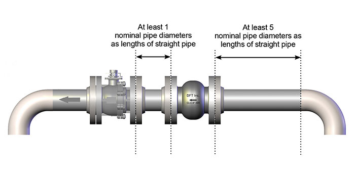 Image 2. Suggested check valve installation when close to pumps, elbows or expansion joints.
Rule No. 3: Find the proper placement.
A common question is whether horizontal versus vertical line placement matters. A horizontal line is always preferred, because it takes gravity out of the equation. While many styles of check valves will work in horizontal piping, axial flow, or silent, check valves are typical in vertical piping.
Common Pipeline Design Mistakes
Trying to cram valves into small, tight spaces is a mistake that should be avoided. Images 1 and 2 demonstrate a few design rules that follow commonly accepted piping practices.
If pumps, elbows, expansion joints and other valves are upstream of a valve, it can cause turbulence, which can lead to instability of the disc and ultimately lead to wear and component failures.
Installing Swing Check Valves in Vertical Pipe Runs
If the flow in the vertical line is going upwards (against gravity), gravity will cause the disc to slam against the seat when the flow stops, potentially leading to water hammer. If flow is going downwards, a swing check valve will always be open and not doing its job. However, axial flow check valves perform well in vertical piping locations.
In vertical piping, the easiest thing to do is replace the swing check or double door valve with an inline, axial flow-style check valve. The stronger spring of the axial flow valve will ensure that the valve closes before the reverse flow happens. Closing the valve before flow reverses can eliminate most water hammer.
Axial-style check valve springs are sized differently for flow down versus flow up. Flow up can often use a standard cracking pressure spring.
Flow down requires a stronger than standard spring to compensate for the weight of the disc, as well as any static head of the media you may want to keep above the disc.
Low Cracking Pressures
Cracking pressures can be easily accommodated in axial flow check valves, up to a point.
A 3-inch check with a 0.1 pounds per square inch (psi) cracking pressure is possible, but a 30-inch valve with a 0.1 psi cracking pressure is not.
This is a common problem with screwed end valves. Pipe sealant (aka, pipe dope) will migrate into the internal areas of the valve.
This sealant material will cause the sealing mechanisms inside the valve (disc and seat) to not seal and may also cause the valve to stick open or closed.
Unscrewing the Valve During Installation
The body halves of a screwed end valve (check valve, ball valve, etc.) may become unscrewed if the valve is unscrewed from the line.
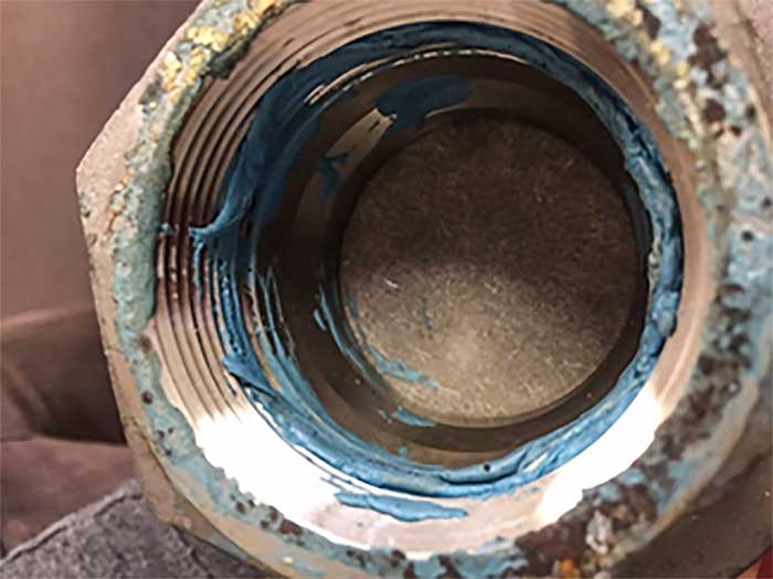 Image 3. Unscrewing the valve during installation
Always put the wrench on the proper end of the valve if it has to be unscrewed from the line. The effect of unscrewing the valve from the line could result in a body seal leak because of a pinched body seal O-ring.
Pay attention to flow direction in the piping before installing the check valve.
End users may wonder if the valve needs to be in a perfectly level pipeline. While it is not necessary, it is preferable. Swing check and tilting disc check valves generally have the seating surface machined on a 5-degree inclined plane relative to the valve centerline. Any angle of the line greater than 5 degrees may cause the disc to not touch the seat and, hence, leak. Axial flow valves do not experience this problem because of the internal spring.
Bonus tip: Clean out the lines before buttoning up the pipeline. This may seem obvious, but end users would be surprised by what gets left in a pipe during construction—weld rod, wrenches, two-by-fours and more. It all damages seating surfaces and delays startup.
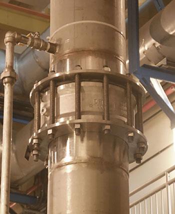 Image 4. Check valves installed in a vertical flow up position.
Valve Maintenance Guidelines
Another common question asked is if oils, greases and lubricants should be used when performing maintenance on valves. Follow the manufacturer’s recommendations and read the maintenance instructions before starting.
Whenever possible, it is generally advisable not to use greases or lubricants as their presence may be detrimental to the process.
Thoroughly clean the valve while it is on the bench for maintenance. The cleaner, the better.
Greases and lubricants, loose rust or scale on cast surfaces, all need to be removed to ensure that the valve will work as well once installed as it did when it was rebuilt and tested on the bench.
Try to obtain the maintenance instructions for the valve being worked on. Even seasoned industry professionals that have been rebuilding valves for 30 years should check to see if the manufacturer has special requirements.
It is better to do the repair right the first time than to have to do it all over again later.
Location Factors
Thinking back to Rule No. 1 and Rule No. 3, try to find the optimum locations in the system for the valves to be installed. Squeezing them in somewhere will only cause issues later.
check valve sizing is important. Remember that the check valves specified and installed will all be opened with the flow of the media. Do not just specify the valve size by the line size. Do the math and get it right.
Generally, the valve body material will match the pipe and flange material. Carbon steel is the most common body material, but there are many choices within this family that are based on external environmental conditions as well as process temperatures.
Trim materials are usually selected to be more corrosion resistant than the body. Hard facing is selected when there may be erosive concerns with solids in the media stream. If the media has solids in it, then the sizes of those solids must be determined, even if they are small (fines) but especially if they are more than 10 percent of the NPS.
Important Gasket Information
The gaskets in the piping system are as critical as the valves themselves. Choose the right materials based on temperatures, pressures and chemical compatibility.
Proper installation is extremely important as well. With all the focus on fugitive emissions, the gaskets have to be considered as well as any stem packings.
If you work on cars, you know about the importance of installing gaskets correctly, particularly if you do not want oil drips or fuel leaks. It is no different for processing piping system gaskets.
Lubricating the bolt threads, nut faces and washer faces is important, but the pre-tightening step is probably the most important because it stabilizes the flanges and keeps them parallel. They should be tightened to a patterned sequence.
Using reliable gasket installation practices achieves several things: uniform bolt loads, uniform gasket stress and uniform flange stress. These are all crucial for tight gasketed joints.
Most importantly, this increases the life of the gasket, and secondarily, it will reduce leakage, which means reduced maintenance and reduced emissions. This leads to more productivity for the plant and makes the plant more environmentally compliant.