
Minimizing downtime for vital pieces of pumping equipment can pose a challenge, even when spare parts are easy to source. Achieving the same goal for legacy equipment would appear almost impossible when spare parts are no longer stocked. However, cutting-edge design and manufacturing technology can minimize delays and offer improved performance. Reliability and efficiency are essential for effective pump performance, but every asset will eventually succumb to wear, erosion, corrosion or fatigue. At this point, operators are reliant on the availability of parts, and in some cases additional engineering support, to complete a satisfactory repair and return the asset to normal operation. Many critical processes use redundant equipment to maintain productivity while an asset is being repaired, but even then, the total repair time needs to be minimized. For those without the ability to engage standby equipment, downtime can represent significant financial costs.
Grasping the Challenge
Pumps are precision engineered for each task they perform, and the impeller consists of complex—and sometimes custom—geometry to achieve the required performance and efficiency levels. It is also under constant attack from the pumped media, and gradually efficiency will be reduced as clearances increase and profiles are eroded. When the time comes to source a new part, the first stop is the OEM, which will always offer replacement parts where possible. In addition, an OEM’s knowledge of pump design and experience in applications should not be discounted when considering the sourcing of a replacement part. Expertise in parts manufacturing and reverse engineering of components can be especially important after sometimes decades of service, when some parts may not be available from stock and lead times become an important factor. Under these circumstances, a specialist parts manufacturer is required, one that can use the original part to reverse engineer the new component. Fortunately, recent advances in engineering technology have enabled lead times to be reduced, along with other advantages.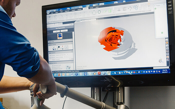 Image 1. Handheld laser scanners can create precision 3D engineering drawings. (Images courtesy of Sulzer)
3D Designs
Creating a set of 3D engineering drawings is now less time- consuming, thanks to handheld laser scanners and digital coordinate measuring machines (CMMs) that can measure items quickly and accurately. When creating replacement parts for crucial pieces of equipment, speed is of the essence. Using the latest generation of laser scanners enables engineers to gather up to 480,000 points of data every second. Intersecting laser lines ensure that even the most complex geometry is captured accurately, which is essential in the recreation of an impeller. For larger pieces of equipment that cannot be easily moved, on-site engineers can visit customers’ premises to offer specialist advice and take essential measurements to create new engineering drawings. Using multiple portable CMMs and laser scanners for on-site data acquisition allow dimensions to be repeatable within 0.025 millimeters (mm). Once basic dimensional data has been acquired, design engineers can then fine-tune the design of the new component. For example, the geometry of an impeller can be adjusted to ensure clearances are optimized. The designers can also make alterations to the original design to account for changes in the application or for performance needs.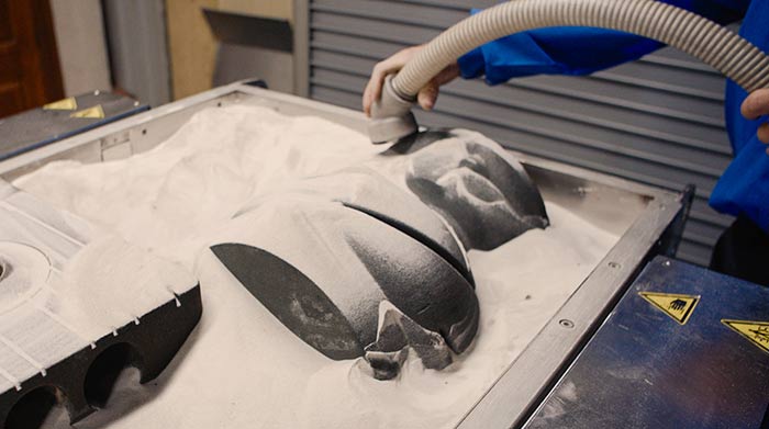 Image 2. 3D sand printers use data to rapidly build a mold of the new component.
Creating the Mold
The traditional process of casting a new component, such as an impeller, required a wooden pattern of the original part to be created and used with a sand-casting box. This is a time-consuming process and can take weeks to finalize the design of the pattern—which can be subject to inaccuracies, especially if it has been stored for any length of time. Today, 3D computer-aided design (CAD) files can be created in minutes using laser scanners, transferred to a wide variety of machine tools and robots, and used to create perfect reconstructions of the original part. One method is to use a 3D sand printer that uses the data to build a mold of the new component. Using layers of sand and adhesive, the 3D printer can create a mold that can withstand the high temperatures of molten metal that will form the new component. As part of this process, design engineers use computational fluid dynamics to predict the flow of gases within the mold as the molten metal is poured. It is essential that the gases have effective escape routes, or vents, since trapped gases would lead to weaknesses in the new component. The vents can be incorporated into the 3D CAD drawing and included easily in the sand printing process.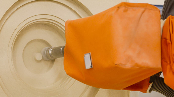 Image 3. CNC robotic milling tools create precision molds from a solid block of sand.
Rapid Manufacturing
State-of-the-art additive manufacturing technology provides complete precision molds and cores. The process takes about 48 hours to complete but, depending on the size of the components, multiple molds can be printed at the same time, making it more efficient. Another method of creating a mold—often used for making casings—involves two halves known as the cope and the drag, which are brought together for the finished shape. The process starts with a block of sand that is machined using a multi- axis computer numerical control (CNC) robotic milling tool to create a precision mold as laid out in the 3D CAD drawings. Producing a wooden pattern for the sand-casting box using traditional methods can take two to six weeks, depending on the complexity of the pattern form. Using a 3D sand printer removes the need for a pattern as the mold is printed directly and finished in less than 24 hours. Machining a precision mold from a sand block takes two to four hours.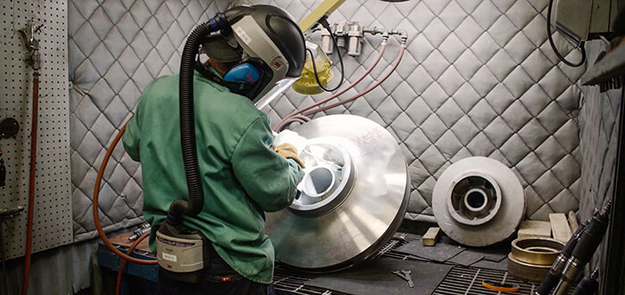 Image 4. Final surface-finishing of complex components is done by hand.