
Nearly every commercial and industrial facility in the world pumps water. Pumping cold, lubricating water is normally straightforward and only requires standard materials seals and lower-pressure components. However, as water is heated, its properties drastically change, and the pump specifications should change as well. At 68 F, water has a specific gravity of 0.9982, a viscosity of 1 centipoise (cP) and a vapor pressure of about 0.3 pounds per square inch absolute (psia). At 176 F, water has a specific gravity of 0.9716, a viscosity of 0.355 cP and a vapor pressure of nearly 7 psia. Hot water is lighter, thinner and less lubricating and vaporizes to a greater degree. Weight and viscosity continue to decrease as the temperature increases. Above the sea level atmospheric boiling temperature of 212 F, the pressure to maintain water as a liquid increases dramatically (see Figure 1).
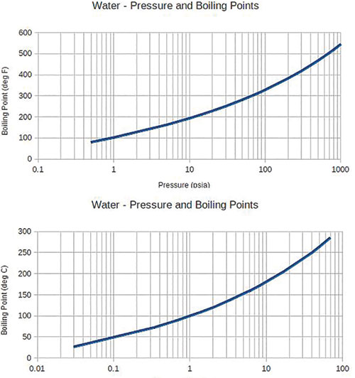 Image 1. A new bronze pump inducer (left) is subjected to severe suction cavitation (right). [Image courtesy of Ceco Environmental, Met-Pro Global Pump Solutions (Dean Pump)]
The Effect on Pumps
The net positive suction head available (NPSHA) should be checked before pumping any liquid, especially hot liquids. Centrifugal pumps require that all incoming streams be in liquid form, so the liquid must not reach its vapor pressure. In most water systems with temperatures higher than 212 F, the water in a vessel or boiler is in a state of equilibrium—the pressure at the water’s surface is the same as the liquid vapor pressure. At the pump suction, the only energy keeping the water liquid is the vertical head measured from the liquid surface to the centerline of the pump impeller. Worse, some energy is lost because of friction in the suction piping. The available energy is best expressed as NPSHA, which is the difference between the pressure at the pump suction nozzle and the liquid vapor pressure.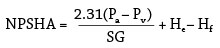 Where:
Pa = pressure at the water surface in psia
Pv = vapor pressure for the fluid at the given temperature in psia
He = difference in height from water surface to the pump suction centerline in feet
Hf = suction line friction loss in feet
SG = specific gravity of the fluid
Hot water systems tend to have low NPSHA, which puts them at risk for cavitation at the suction eye of the impeller. As the liquid accelerates through the suction pipe, pressure drops. Bubbles will form as the liquid drops toward its vapor pressure.
After the bubbles enter the impeller eye, the pressure begins to increase and the bubbles collapse. The collapsing bubbles produce tremendous localized pressures on the impeller’s surface and remove small amounts of metal. The tiny abrasions occur constantly as the liquid moves through the pump and, over time, will severely reduce the structural integrity of the metal. When pumping water, cavitation typically sounds like rocks hitting the impeller (see Image 1).
Where:
Pa = pressure at the water surface in psia
Pv = vapor pressure for the fluid at the given temperature in psia
He = difference in height from water surface to the pump suction centerline in feet
Hf = suction line friction loss in feet
SG = specific gravity of the fluid
Hot water systems tend to have low NPSHA, which puts them at risk for cavitation at the suction eye of the impeller. As the liquid accelerates through the suction pipe, pressure drops. Bubbles will form as the liquid drops toward its vapor pressure.
After the bubbles enter the impeller eye, the pressure begins to increase and the bubbles collapse. The collapsing bubbles produce tremendous localized pressures on the impeller’s surface and remove small amounts of metal. The tiny abrasions occur constantly as the liquid moves through the pump and, over time, will severely reduce the structural integrity of the metal. When pumping water, cavitation typically sounds like rocks hitting the impeller (see Image 1).
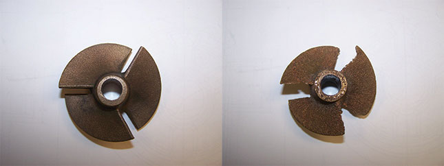 Image 1. A new bronze pump inducer (left) is subjected to severe suction cavitation (right). [Image courtesy of Ceco Environmental, Met-Pro Global Pump Solutions (Dean Pump)]
Other Properties
After determining the NPSHA, the end user should consider the additional effects of hot water on pump performance. Most centrifugal pumps can handle water temperatures up to 250 F. At temperatures above 300 F, pumps and piping systems start to expand dramatically. The American Petroleum Institute (API) Standard 610 recommends that pumps in this temperature range and above should be designed with centerline-supported casing. This design feature allows the pump to thermally expand from its center of rotation, keeping the rotating components on the same axis with the pump casing. The pump casing can expand freely without being fixed vertically to the pump base. The centerline-supported casing significantly reduces the pump alignment problems of foot-mounted casing designs. The pump casing, bolts and flanges should be designed to withstand 150 percent of the pump’s working pressure: Pwp = 1.50 (Pt + Ps) Where: Pwp = pump design working pressure in psig Pt = total developed pressure or differential head in psig Ps =suction pressure in psig For a centrifugal pump, the lower density of hot water reduces the horsepower required for a given flow and head. The resulting reading on a pressure gauge will also be reduced because the column of liquid weighs less and the resulting pressure is lower. The lower viscosity at higher temperatures reduces the film thickness between the mechanical seal faces, leading to more friction and less lubrication. This is compounded by the increased internal working pressure, which forces the seal faces together. As a result, sealing becomes more difficult as the temperature of the liquid rises. As water is heated, the vapor pressure at higher temperatures will significantly increase system pressures. Sealing the hot water becomes a challenge as the difference between the stuffing box and atmospheric pressures increases. Seal failure will allow the hot water to escape at high pressures, creating a dangerous environment.Cooling the Seal
Just as leakage is needed for packed pumps to properly cool and lubricate the shaft packing, a small amount of seal leakage is necessary to lubricate and cool the mechanical seal faces in mechanically sealed pumps. The mechanical seal leakage—normally not visible and in vapor form outside the pump—cools and lubricates the mechanical seal faces. A balanced mechanical seal is required for temperatures higher than 220 F. An unbalanced seal may be used for temperatures lower than 220 F. For an unbalanced seal, one face’s material should be a special hot water carbon (Code P66 or F48), and the other face should be tungsten carbide (Code 015) or silicon carbide (Code 58). The static seals should be elastomeric O-rings, although elastomers do not perform at their normal temperature ratings in hot water. The recommended maximum temperature limits for hot water applications are 250 F for Viton, 280 F for Ethylene Propylene, 350 F for Aflas and 400 F for Kalrez. The most common mechanical seal recommended for high-temperature water has Aflas elastomers, hot water carbon versus tungsten carbide seal faces and 316 SS hardware. The seal chamber should be cooled if temperatures rise above 250 F. A seal chamber cooling jacket, though helpful, will not be adequate. A cooled flush over the seal faces should be considered.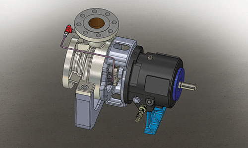 Figure 2. A flush line can effectively remove heat from the seal faces. [Image courtesy of Ceco Environmental, Met-Pro Global Pump Solutions (Dean Pump)]
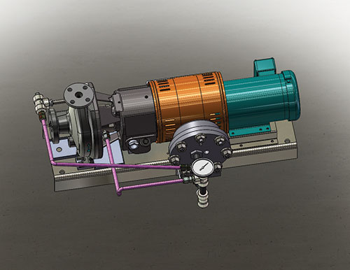 Figure 3. The API Plan 21 (ANSI Plan 7321) [Image courtesy of Ceco Environmental, Met-Pro Global Pump Solutions (Dean Pump)]
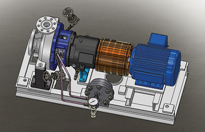 Figure 4. The API Plan 23 (ANSI Plan 7323) [Image courtesy of Ceco Environmental, Met-Pro Global Pump Solutions (Dean Pump)]
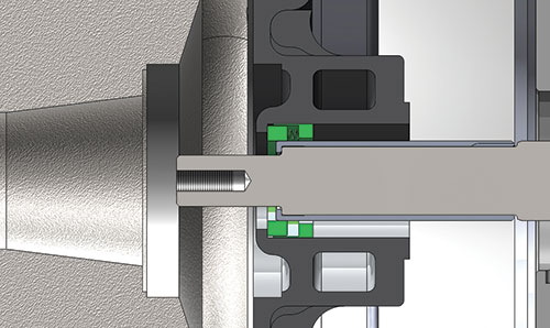 Figure 5. The minimum flow bushing limits the flow through the stuffing box. [Image courtesy of Ceco Environmental, Met-Pro Global Pump Solutions (Dean Pump)]
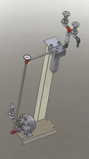 Figure 6. The seal system includes ANSI Plan 7321 (API Plan 21) with a filter to remove particulate. [Image courtesy of Ceco Environmental, Met-Pro Global Pump Solutions (Dean Pump)]