Q. How does axial thrust compare among different impeller types for a rotodynamic vertical pump?

A. The net axial downthrust force is carried by the pump shaft. The shaft will stretch, or elongate, under this load. Before the pump starts up, any stretch that occurs is due to rotor weight, the sum of the static forces. The thrust load will increase after the pump starts up due to the addition of the dynamic forces.

The dynamic forces creating thrust on a vertical turbine pump enclosed impeller (see Figure 2.3.3.2.3a) are due to the difference in pressure distributions on the upper and lower shrouds along with the force from the change in momentum of the flow through the impeller.

Enclosed impeller plain top shroud
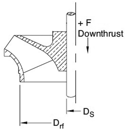
Figure 2.3.3.2.3a. Enclosed impeller plain top shroud

The semi-open impeller (see Figure 2.3.3.2.3b) has only an upper shroud. The difference in pressure distributions along the backside and vaned side of the shroud is typically greater than between upper and lower shrouds of an enclosed impeller. Semi-open impeller axial thrust is higher than that of the enclosed impeller.

Semi-open impeller
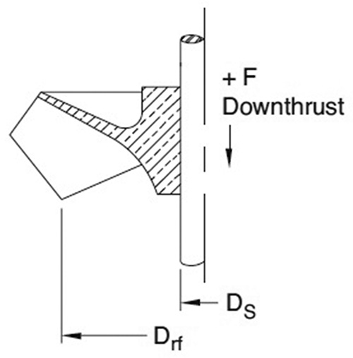
Figure 2.3.3.2.3b. Semi-open impeller

The axial flow pump impeller (propeller) has no upper or lower shroud. The vanes are attached directly to the hub. The axial thrust generated is primarily from dynamic forces created by the interaction of the propeller vanes with liquid.

The impeller back ring with balance holes configuration (see Figure 2.3.3.2.3c) reduces axial thrust. Back rings may be cast integrally into impellers with a top shroud. They are used when pump total axial thrust requires reduction. The flow through balance holes in the impeller hub shroud, combined with the leakage past the balance ring, reduces efficiency. The exact efficiency reduction depends on the individual design, pump size and specific speed. The effect of increased leakage through the clearances because of wear of the back ring arrangement may be an increase in downthrust and should be considered in sizing the thrust bearing.

Enclosed impeller with back ring and balance holes
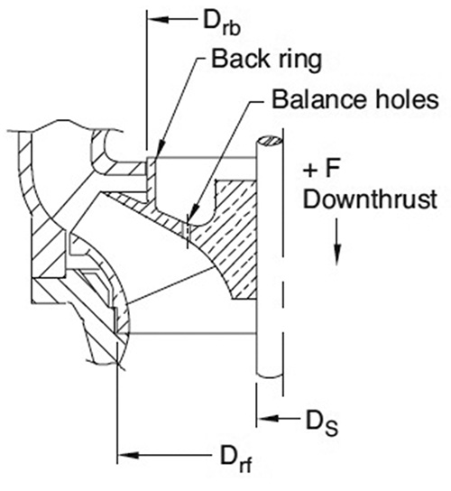
Figure 2.3.3.2.3c. Enclosed impeller with back ring and balance holes

For more information about axial thrust for vertical rotodynamic pumps, see ANSI/HI 2.3 Rotodynamic (Vertical) Pumps for Design and Application.

Q. How is the net positive inlet pressure required found for a rotary pump?

A. Net positive inlet pressure required (NPIPR) for a rotary pump is difficult to establish with precision because of compounding external influences of fluid properties and dissolved and entrained gas, all of which affect the measured NPIPR. The level of dissolved gas is a function of the fluid and its temperature and is also a function of the system design operation.

Many liquids handled by rotary pumps have an unpredictable or low vapor pressure. Most of these liquids also have entrained and dissolved gas (frequently air). The practical effect of dissolved and entrained gas is to increase the NPIPR to suppress the symptoms of cavitation. While true cavitation occurs if the liquid pressure falls below its vapor pressure during filling of the pump cavities, most of the cavitation symptoms will be exhibited before reaching liquid vapor pressure. This is largely because of the entrained and dissolved gas expanding when subjected to reduced pressure.

Normal NPIPR tests are conducted in a test environment that minimizes entrained gas. NPIPR can be established at the first indication of any of the following:

  • A 5 percent reduction in the rate of flow at constant differential pressure and speed
  • A 5 percent reduction in power consumption at constant differential pressure and speed
  • The inability to maintain a stable differential pressure
  • The onset of loud or erratic noise when these criteria are previously agreed on by all parties

For further information on NPIPR for rotary pumps, see ANSI/HI 3.6 Rotary Pump Tests.

Q. What is a hydraulic-coupled tubular diaphragm as it relates to controlled-volume metering pumps?

A. A hydraulic-coupled tubular diaphragm liquid end (see Figure 7.6) contains a flexible tube, clamped at both ends, that is in direct contact with the process liquid being displaced.

Hydraulic tubular diaphragm
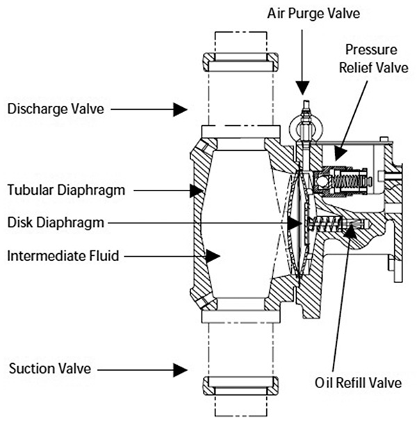
Figure 7.6. Hydraulic tubular diaphragm

This type liquid end design is inherently leak free. The diaphragm material is either perfluoroalkoxy (PFA) or an elastomer.

These liquid ends are typically used for viscous liquids or slurries. In operation, the plunger moves rearward and through, and the hydraulic coupling expands the tube, admitting liquid into the tube’s cavity through the suction check valve.

As the plunger moves toward the wet end, the hydraulic fluid constricts the tube, moving the process liquid through the discharge check valve. A disk diaphragm constrained by contour plates may be used in series hydraulically.

This disc diaphragm is used to ensure that the tube operates within its elastic limits.

For further information about hydraulic-coupled tubular diaphragms, see ANSI/HI 7.1-7.5 Controlled-Volume Metering Pumps for Nomenclature, Definitions, Application, and Operation.