
An aggregate production company saves more than $30,000 annually with new installation efficiency and productivity increases.
02/21/2014
A large California construction company with more than 5,000 employees had a seepage problem. The company is one of the top 10 producers of aggregate and sand/gravel products. It often extracted aggregate material for road construction and other uses from a gravel pit. While the pit was a great source of materials for concrete production, it had one big problem—it frequently filled with water. While Northern Californian rains contributed to the water retention issue, the main culprit was an underground river. Water seeped into the pit from this river, filling it with dozens of feet of water in a day. When filled with water, extraction had to stop, and the water had to be pumped out to manageable levels.
Initial Fixes
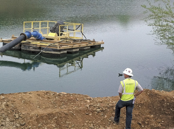
The company installed some pumps on barges to attack the seepage. These pumps moved the water away from the pit and into a retention/holding area. If all had worked as planned, the barges would keep the water level low enough so that extraction could occur continuously. Unfortunately, that was not the result with the pump barges. The vertical cantilever pumps were not adequately dewatering the pit. The expected flow rates were not met, and the water level did not fall to a level at which extraction could be easily accomplished. Rocks and debris frequently blocked the pumps, causing maintenance shutdowns. The pumps also experienced frequent vortexing, entraining air and operating inefficiently. As the company extracted more gravel, the bottom of the pit moved closer to the underground river, increasing the seepage..jpg) The new dewatering pump
The new dewatering pumpRequirements
The dewatering solution required that the pumps work as efficiently as possible. Because of the high cost of electricity in Northern California, even a few percentage points difference added up to a much higher energy bill. The pumps needed to push up to 18,000 gallons per minute (gpm) from the pit, and they needed at least 250 feet of head to move the water to the retention/storage area. The system also had to be reliable. The company could not stop the pumps and pull in the barge because of mechanical issues. The pumps had to be able to handle solids, such as pieces of wood, from the bottom of the pit. Preferably, the system would not require mechanical priming to mitigate one more possible mechanical system failure concern.The Solution
A distributor for a pump provider visited the site to better understand the hydrology of the situation and offer different solutions. Replacing the cantilevered sump pumps was explored, as well as the possibility of mounting pumps on the edge of the pit. Mounting pumps on the edge seemed impractical because of net positive suction head available (NPSHa) concerns. The pump would require frequent restaging to the proper elevation because of the changes in the pit’s water level. The vertical cantilevered slurry pumps that were examined required a much deeper minimum submergence than was available because of the water’s varying levels. The pumps were also not very efficient and had a relatively high net positive suction head required (NPSHr). Maintenance and parts availability were also issues.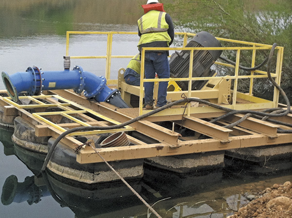 Workers at the aggregate company prepare the newly outfitted barges with the dewatering pumps.
- The pumps could operate without drawing in as much debris and particulates, which clogged the vertical pumps. If the pumps pulled in debris, they had a solids-handling capability of 4.75 inches.
- NPSHr was minimized, reducing the chance for vortexing and allowing the pumps to operate in relatively shallow conditions.
- The pumps were able to maintain their efficiencies—operating at an impressive 82.5 percent.
- The system did not require mechanical priming.
Conclusion
The pumps have been installed since March 2012 and have functioned well. The company reports that they are efficient and quiet. Most important, electricity is one of highest cost components in creating concrete from the mined aggregate. Through the dewatering pump’s superior efficiencies, the mining company has saved more than $30,000 in energy and maintenance costs per year. The company’s plant manager said that the pumps will improve efficiency while providing a quick payback on the upgrade costs. The direct-drive configuration will reduce maintenance, which is difficult because of the floating configuration. The operators have been impressed with the pumps’ performance. The speed with which they are able to lower the water level when needed has exceeded their expectations.Vortexing
One significant problem with this installation was the tendency of the vertical turbines to vortex in the pit. Similar to cavitation, with the loss of efficiency and damage that can occur to the pump, vortexing is the result of too much water relative to the pit/sump depth being drawn into the suction line. A depression forms on the surface of the water and is commonly seen as a whirling vortex. Many have seen a whirling vortex form when a sink or bathtub drains. As the water level in the tub decreases, the ferocity of the whirlpool increases, with a column of air often visible all the way into the drain. A noticeable whirl on the surface of the body of liquid being pumped does not need to be perceptible to human eyes to cause damage, and in the worst cases, a column of air can lead straight into the suction pipe. Vortexes form between the pump suction and intake tank fluid surface. This causes air to enter the pump suction, and the entrained air reduces pump capacity and efficiency. Excessive shaft deflection is also produced by the entrainment. The pump’s mechanical seals, bearings, piping, couplings and impeller can be damaged by the vortex condition. Ideally, vortexing can be anticipated in the design phase and eliminated with the proper amount of suction for the water level. However, if a pump experiences vortexing, the issue can be reduced or stopped by changing the velocity of the water entering the pump. Reducing or eliminating vortexing can be accomplished through:- Increasing the size of the inlet piping or installing a flared suction line
- Increasing the depth of the fluid source (or raising the pump to increase the distance between the bottom of the fluid source and the intake)
- Reducing the pump flow rate
- Operating at a different level to reduce head
- Slowing the system
- Reducing the number of pumps running in the fluid source
- Using diffuser screens or baffles
- Alerting the fluids/solids ratio in the intake
- Realigning the return line to reduce a waterfall effect in the liquid source
- Floating large balls on the surface to dissuade vortex formation
- Cleaning the trash screen to remove restrictions
