

Boiler feed pumps (BFPs) consist of feeding to a steam generator (e.g. boiler) a quantity of feedwater corresponding to the quantity of steam generated. Operating parameters (flow, head, temperature) of boiler feed water are calculated by a boiler designer.
Today, almost all BFPs are centrifugal pumps. The construction of BFPs in respect to shaft power, material, pump types and drive are governed by the developments which have taken place in power technology. The trend in fossil fuel power stations is continuously towards larger power block units.
Until 1950, the average discharge pressure of BFPs was in the 200 bar region. By 1955, it had risen to 400 bar. Mass flows were in the region of 350 tons per hour (t/h) in 1950 and have risen to 2,500 t/h (4,000 t/h) in conventional power plants. BFPs operate at temperatures of 160 C to 180 C, and in exceptional cases,
even higher.
BFPs were constructed of unalloyed steels through the 1950s. Since then, 13% to 14% have pivoted to chrome steel (A743 Gr. CA6NM). This change in materials was made necessary by the introduction of new feedwater treatment processes. The development of high strength, corrosion-resistant chrome steels with emergency running characteristics paved the way for the current BFP with speeds of 5,000 to 6,000 rotations per minute (rpm). The flow rate of BFPs rose with the rise of power block outputs. Today’s full-load BFPs for traditional 750 megawatt (MW) power trains are constructed with four to five stages, with stage pressure up to 80 bar.
Electric motors (asynchronous motors) are used to drive the feed pumps. Speed adjustment of an electrically driven BFP is possible to achieve by several means, including using fluid coupling, variable frequency drive (VFD) into motor and gearboxes. If a plant has abundant steam available, a steam turbine can also be used for the driver unit. In several cases, condensing turbines running at 5,000 to 6,000 rpm are used. However, using condensate-type steam turbine increases the requirement of equipment into the train. It is essential to use a heat exchanger, condensate extraction pump or the like for effective use of the unit.
If a BFP is needed for high pressure and high rpm, a booster pump is required. In such a case, adequate net positive suction head available (NPSHa) is difficult to achieve and the booster pump fulfills the requirement. For reducing the net positive suction head required (NPSHr), it is possible to select the pumps making first stage (suction) as a double suction. NPSH is most significant at the suction stage only.
There are two types of construction mostly used for BFP application. One is a multistage barrel type pump, which is defined as a between bearings (BB) 5 type pump per American Petroleum Institute (API) 610. The other is a ring section multistage pump which is defined as a BB4 type pump. However, a ring section pump does not meet the criteria of
API 610, making it an exception. In some cases, axial split multistage pumps can also be used. It is defined as a BB3 type pump under API 610.
Barrel type pumps are used for high-pressure designs, but this can vary by user. Due to some advantages over ring section pumps, plant users tend to prefer to use barrel type pumps even though it is a high investment in the beginning. If a barrel pump needs to be taken out for repairs, the rotor must be replaced, but the casings (barrel) can remain in place with the suction and discharge piping. This is important regarding the availability for service of the power backup, if there is no 100% standby pump installed.
Casing Of Pumps
The pump casings of BFPs must be considered from two points of view: the wall thickness must be sustainable on one side to satisfy the pressure loading requirement and the other side needs to adapt itself to the temporary temperature variation which arises.
Barrel casings are usually made of ductile forged steel, and all surfaces in contact with the feed water are coated with the austenitic material by cladding process. To weld the pump casing into the pipeline, an intermediate piece made compatible for welding into the pipeline and the pump casing is welded onto the pump suction and discharge branches. The cover on barrel pumps are sealed by flattening a cellular metal spiral-wound gasket (sealing).
The casings of ring section pumps are constructed from cast or forged carbon steel—sometimes cast iron—depending on the application and requirement defined by the user. The sealing of each casing (stages) against one another is by metal-to-metal contact—the individual casings being clamped together axially by tie bolts between the suction and discharge pump casings. Metal-to-metal contact is one of the drawbacks of the ring section pump, as it restricts the use of the pumps in high temperature applications. Temperature shocks are absorbed by additional stresses on the tie bolts and sealing faces of the stage casings.
The casings of axial split pumps are divided into two parts, lower and upper. The casing dismantles vertical to the shaft. These pumps have an advantage on thrust balancing as the number of stages can be mounted in the way to opposed way of direction. It balances the thrust with minimum effort.
Usually, BB3 type pumps are recommended to use up to the fluid temperature limited to 200 C or less. API 610 has clear guidelines if the pumping temperature is 200 C or higher, radial split casing pumps are to be used. An important note: casing bolts are not considered wetted part in this pump due to axial split arrangement.
Water injection at a pressure situated between the suction and discharge pressures of the pump is a frequent service requirement. This is taken care of by tapping water from one of the pump stages—both in the case of barrel pumps and ring section pumps. These pressure zones are sealed off from one another by flexible spiral-wound gaskets and the flexibility and thermal shock behavior are suitably matched to one another.
Rotor Construction
BFPs are fitted with pump shafts, which have an appropriate distance between bearings and are combined with a large shaft diameter. The impellers are usually shrunk on the shaft, and consequently the static shaft sag is small. The shaft is insensitive to vibrations, and in normal running conditions, is smooth without any undesirable radial contact with the casing. The hub diameter is increased at the back of the impeller, and the impeller entry geometry is designed to keep the diameter as small as possible to reduce the axial forces which must be absorbed by the balancing device.
Balancing of Axial Thrust
In a multistage pump (barrel type of ring section type), impellers are arranged on long shaft (depending on stages) and between bearings. This arrangement is the cause of producing thrust. When the pump starts, flow moves from suction to discharge (low pressure zone to high pressure zone), and after arriving at discharge, 100% pressure cannot be discharged and thrust generate towards suction. However, during operation of the pump, the magnitude of this axial thrust will depend on the position of the operating point on the throttling curve and amount of the wear on the internal clearances.
Additional disturbing forces can arise if pumps are operating in abnormal conditions. For example, if the pump starts to cavitate, it means the NPSH is not sufficient to run the pump smoothly. On the larger BFPs, the balancing of the axial thrust on the pump rotor is affected by means of a balancing device through which the pumped fluid flows, combined with an oil-lubricated thrust bearing. The hydraulic balancing device may comprise a balance disc with balance disc seat, or a balance piston or double piston with the associated throttling bushes. Pistons and double pistons can also be combined with a balance disc. It is important to note API 610 does not allow the use of a balancing disc, so a drum should be used. However, API 610 strictly pertains to petrochemical, oil and gas applications. In several cases, plants have prohibited the use of a balancing disc for the BFPs in typical power plants.
Balancing of Radial Forces on the Pump Rotor
Radial forces arise from the weight of the rotor, mechanical out-of-balance and radial thrust. The balancing of the radial forces is affected by two oil-lubricated radial bearings and by throttling gaps by which fluid flows axially. These throttling gaps through which the fluid flows axially are located at the impeller neck, or in the case of multistage BFPs, in conventional power stations in the throttling bushes of the diffuser plates and on the balance piston. If the rotor is slightly eccentric, a centering restoring force will be generated in these gaps, and this force will be dependent on the pressure differential and on-the-gap geometry. This restoring action is usually called the Lomakin effect. It is reduced when the headwater in the gap flow is not in a purely liquid phase. The hydrostatic action of the throttling gaps in respect of mechanical stiffness can exceed the shaft stiffness. The system is tuned in a way that the critical speed of rotation always remains away from the operating speed. Hydraulic exciting forces, particularly under part load operation, can be absorbed in addition.
Shaft Seals
Soft-packed stuffing boxes, mechanical seals, floating seals and labyrinth seals can be used on BFPs for sealing purposes. The application limit of soft-packed stuffing boxes is governed by the existing possibilities for the removal of frictional heat. In the case of high duty, soft-packed stuffing boxes, there is usually a precooling of the leakage water and an ambient of the stuffing housing, shaft protection sleeve and gland. The packing material usually consists of braided Teflon twine. This shaft seal is used with success on full load feed pumps up to 150 MW power train capacity.
The small leakage of mechanical seals is emitted into the atmosphere in the vapor form at the exit. The frictional heat generated is less than in the case of soft-packed stuffing boxes. A closed-circuit cooling system is generally adopted—which is driven by a circulator device on the rotating seal ring when the pump is running and by thermosiphon action when the pump is stopped.
A floating seal can be used for high circumferential velocities and high sealing pressures. The floating seal consists of a series of short throttling rings which can be displaced radially. A stream of cold sealing water is injected into the seal to ensure that no hot water can leak out of the pump. This sealing water feed must be kept going while the pump is running under pressure. The control of the sealing condensate injection into a floating seal can be affected by differential pressure, regulation or by differential temperature regulation of the sealing condensate.
Single Acting Mechanical Seal
In case of high temperature application, more than 80 C, use a single acting mechanical seal with the cooler which is classified as Plan-23 as per API 682.
Warming Up Pressure
If BFP is switched on and off frequently, it is desirable to avoid thermal shock and warping of the casing after the pump has stopped to prevent premature internal wear at the sealing gap. In principle, the construction materials are selected in such a way that the BFP can be started up from any thermal condition. However, a physical contact between rotor and casing at locations with a close clearance cannot be avoided under certain circumstances of abnormal operation—e.g., when cavitation occurs, or during a semi-warm start, when the BFP is warped. The affected locations are the throttling gaps at the impeller inlet, the throttling bush in the diffuser and the balancing device. The matching of appropriate construction materials at these locations, consisting of corrosion-resistant chrome steels with special alloy additions ensures good emergency running conditions even at high circumferential velocities. Any high wear at close clearance gaps is always linked with a drop in efficiency.
Minimum Flow Valve
A so-called minimum flow valve (e.g., an automatic leak-off valve, valves, and fittings), is arranged downstream of the outlet pipe if the BFP ensures that a minimum flow is always present and prevents any damage that might arise during low load operation, as a result of excessive overheating and evaporation of the contents of the pump, or as a result of cavitation at part load operation.
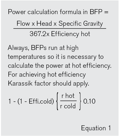
Some additional points to be learned while study of boiler feed water pump are in Equation 1:
Essential fundamentals to emphasize for BFPs are proper pump warmup, standby warming and shaft (fixed bushing) seal drain temperature control. These characteristics have become more critical as central station plants are cycled and large feed pumps are operated with varying loads and in standby modes. Prewarming of the pump and maintaining warmup flow to an idle pump to assure dimensional thermal uniformity is essential to maintenance of internal clearances, pump efficiency and long life. This process is critical for multistage pumps to minimize thermal distortion. The distortion will cause the following potential failure modes: flashing, internal rubbing, increased wear ring clearances, pump seizure, worn seal bushing clearance and excessive leakage, loss of pump performance and efficiency, high pump vibration and worn bearings/bearing clearances.
Installation features and practices that extend life, efficiency and reliability are:
- Proper pump insulation at the casing and discharge head
- Warmup orifice, piped around the discharge check valve.
- Maintaining shaft seal leakage drain temperature between 150 F and 170 F (65 C and 77 C); use an electro-pneumatic temperature control system.
- Installation of thermocouples or other temperature-detecting instruments in the pump casing and discharge head to confirm temperature differences within 50 F (28 C) across the pump and relative to the feedwater temperature.
- Assurance of proper functioning of the pump casing pin and key block to allow uniform thermal growth. Confirm that the hold-down bolts for the outboard casing feet are not over-torqued.
- Assurance of proper location and functioning of critical pipe hangers to minimize pipe strain on the pump suction and discharge nozzles.
References
KSB Lexicon
Pump Handbook by Igor J. Karassik
API 610, API 682
