Common Pumping Mistakes
by Jim Elsey

The first bearing isolator of the current design was patented in 1977 and initially used on pumps and mixers in the food processing and chemical industries. Since the 1980s, they have been installed on most anything that rotates.

During the last 10 to 15 years, most general-service, frame-mounted and horizontal American National Standards Institute (ANSI) pumps include a set of bearing isolators to protect the bearing housing from the introduction of liquids and debris (contamination ingress). Keeping the lube oil clean greatly improves the life of the bearing and, ultimately, the pump.

Bearing isolators/protectors are a marvelous improvement over the previously used devices—lip seals. To a lesser degree, interim devices on higher-energy pumps involved stationary and occasionally rotating labyrinths of both axial and radial designs. Modern bearing isolators consist of a non-contacting unitized rotor and stator combination. Consequently, there should be no wear on the shaft and/or on the isolator itself.

The earlier generation of bearing protection (lip seal designs) had a relatively short operational lifespan that was usually measured in months. The edge of the lip seal contacted the rotating shaft, creating permanent damage.

Bearing isolators are not just designed to keep the contamination out and away from the oil and the bearings; they are also designed to keep the oil in the bearing housing of the pump. If the isolators (and the pumps) are properly installed, they will often operate more than 10 years with no bearing isolator issues. At some point, the elastomers reach the end of their useful life, which is mostly driven by environmental factors.

Given the potential for a bearing isolator with a long lifespan, not all millwrights, operators and mechanics fully understand the limitations and boundaries of the bearing-protection device. Over the last 30 years, I have witnessed frequent errors and a general misunderstanding of the rules and principles for the devices. One of the most common field complaints I hear is that the lube oil is leaking out of the bearing housing.

The following general checklist will help users find and troubleshoot potential reasons for oil leakage (oil egress) from the bearing isolator in the field.

This checklist does not cover all designs and is based on a typical horizontal ANSI (B73.1) pump design because it is the most common type of pump used in general industry.

This discussion is limited to pumps, but isolators/protectors are also commonly used on motors, mixers and other types of rotating equipment. If you have something to add to this checklist, I would appreciate your input.

Proper oil level 
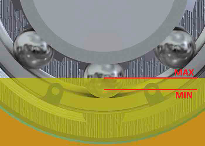
Figure 1. Proper oil level is between one-quarter and one-half of the lowest ball in the bearing housing. There are no advantages to a higher oil level. (Courtesy of the author)

❑ The bearing housing is overfilled (oil overfill). This is the most common problem I witness. The oil level should be maintained at the middle of the sight glass and no higher. This sighted level should correspond with the middle of the lowest ball in the ball bearings, either radial or thrust (see Figure 1). Note that in the case of an oil overfill, it takes some time for the oil to be dissipated from the isolator, so it is important to be patient and continue cleanup of the oil for several days of running after the overfill incident.

❑ The pump is not level. To solve this problem, I recommend using a Starrett or equal machinist-level model 98-6. The pump must be level in both directions (stem to stern and, in nautical terms, athwartships).

❑ The expulsion port (also known as the drain port or, on some models, the weep slot) on the isolator is in the wrong location (installed incorrectly). The isolator must be installed so the expulsion port is at the 6 o’clock position, which is at the very bottom and lowest point. An exception is when the isolator is designed with numerous expulsion ports, as in the case of units designed for the outboard end of an ANSI pump design that uses a reverse-vane-style impeller. These pumps adjust the axial clearance of the impeller to the seal chamber (stuffing box) by rotating the threaded bearing carrier on the outboard end. The bearing carrier contains the isolator, and it could be in any radial position in the process of setting the impeller clearance.

❑ The wrong isolator is installed. For example, a Type A outboard isolator used on a semi-open-impeller-type ANSI pump is placed on a reverse-vane impeller pump on the outboard end. These types have a singular expulsion port.

❑ The wrong isolator is installed (for reasons other than those previously stated). The isolators are the wrong size or of an incorrect material (the temperature of the application and/or chemical environment will dictate different material requirements).

❑ The isolator is installed or reinstalled improperly. See the manufacturer’s installation and operations manual (IOM). Sometimes during maintenance the unitized rotor and stator will become separated. If this happens, contact the manufacturer for advice before attempting to reassemble.

❑ The internal diameter (ID) of the bore on the pump bearing housing is incorrect, or the outside diameter (OD) of the stator is incorrect. Perhaps a bearing failed and turned (spun) in the bore, which will score and destroy the critical clearances. Refer to the IOM and/or factory for proper dimensions and tolerances.

❑ The bearing isolator is installed satisfactorily but is improperly moved (axially). This can occur when adjusting the impeller clearance, measuring total axial clearance, or when the shaft is removed or installed.

❑ The isolator is reinstalled without an O-ring on the OD of the stator (certain types only). Some bearing isolator styles have stator OD O-rings that can be used only once because they are designed to purposefully shear during the installation process.

❑ The constant level oiler (commonly a Trico oiler) is set incorrectly because the cross-nut adjustment is set to the wrong height (in this case, too high), or it is installed in the wrong bearing housing penetration or on the wrong side of the pump. Constant-level oilers are rotationally sensitive for proper operation. There is a correct and incorrect side of the pump on which to install them that depends on the direction of rotation.

❑ The bearing housing is over-pressurized. Potential reasons outside of large temperature swings are too varied and detailed to discuss here.

❑ There is excessive pipe strain. The resultant forces and moments of pipe-induced stress will cause the bearing bore and, consequently, the isolator device bore to be out of round or concentricity. This will also create a non-congruent or offset centerline with the sister bearing. Check for pipe strain by placing dial indicators in two planes on the coupling hub. Release the bolts on one of the pump flanges: If the dial indicator moves more than 0.002 inches, there is excessive pipe strain. Repeat for the other flange. Correct the cause of the stress before proceeding.

cross-section of the bearing protector
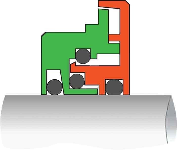
Figure 2. A cross-section of the bearing protector: The green portion is the stator and the orange portion is the rotor (Courtesy of Orion Engineered Seals)

❑ A drivetrain component is too close to the external isolator face. In rare cases and mostly on larger pumps, if a drivetrain component such as a rotating coupling (spinning in the semi-enclosed space of an OSHA guard) is too close to the external face of the isolator, a low-pressure area can form (caused by the air velocity, also known in this case as windage). The low-pressure area creates a differential pressure outside the bearing housing near the face of the bearing isolator. Consequently, the oil can be picked up and moved with the air flow windage. To correct this situation, you can distance the coupling and OSHA guard from each other and/or from the isolator face. An alternate solution in some cases is to use a larger OSHA guard.

❑ The oil sight glass is at the incorrect height (manufacturing or repair facility defect). I saw this issue once on two large end-suction pumps in flue-gas desulfurization service at a power plant.

❑ The bearing isolator may fail or work incorrectly in cases of high vibration on the pump. Excessive vibration could be caused by cavitation, air binding, imbalance, surging, improper operational area and/or misalignment of the driver. Note that vibration is not a likely cause of oil leakage because the bearings and seals will normally fail first.

❑ Occasionally the oil leaks out, but not because of the bearing isolator. During the repair and maintenance cycles, sometimes the bearing housing gaskets are omitted or of an incorrect material or dimension, and/or the bolts are not properly torqued. In rare cases, I have seen porous casting issues contribute to the problem.

❑ The oil gauge is inaccessible. While not necessarily a leak issue, I have seen end users install ANSI pumps next to a wall with the oil sight gauge (indicator) on the wall side of the pump. The operators wanted a direct line of sight to the indicator and removed the sight gauge from the starboard side of the pump and relocated it on the other side (port) of the bearing housing. On almost all ANSI pumps, there is a normally plugged penetration where the finned oil cooler would be located, if used. Both the oil cooler and the sight glass penetrations are sized at 1-inch national pipe thread (NPT). However, the centerline of the cooler penetration is at a slightly lower level than the sight glass penetration.

The result is that the new corresponding oil level will be incorrect and too low. Bearing life will be severely compromised because of inadequate lubrication. Note that some pump manufacturers have penetrations on both sides of the pump bearing housing for the sight glass installation on both sides.

To read other articles in the 'Common Pumping Mistakes' column, go here.