Consider these methods to help protect systems from high-frequency current damage.
ABB

external source
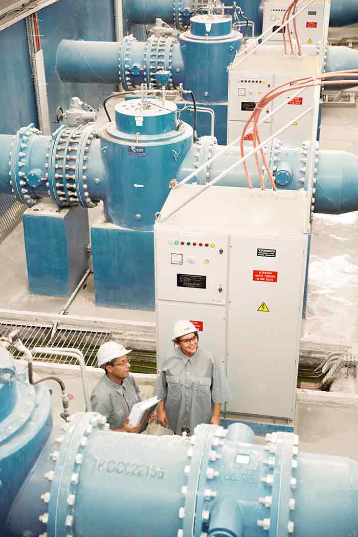
Image 1. An external source of shaft voltage exists for induction motors operated by adjustable speed drives. (Images courtesy of ABB)

Bearing currents have been around in one form or another since Tesla’s invention of the induction motor in 1887. A recent search of the Institute of Electrical and Electronics Engineers (IEEE) Xplore database revealed more than 4,200 papers written and archived discussing this subject. Of these, roughly half were authored in the last 10 years, indicating that the understanding of these currents continues to grow through experimentation and analysis. Understanding the mechanism by which bearing currents are generated provides insight into best practices for remediation.

Bearing currents occur when voltage is induced on the motor shaft that is high enough to overcome the breakdown voltage of the bearing lubricant. There are two typical paths for this current to flow. The first is from the shaft, through a bearing, and through the motor or load frame to ground. The second path is for the current to circulate from one end of the shaft, through a bearing, through the motor frame, into the opposite bearing and back into the shaft.

induced voltage
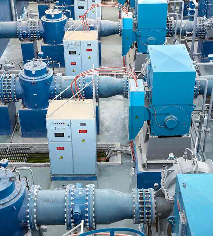
Image 2. Sources of induced voltage on the shaft may vary.

The source of the induced voltage on the shaft can vary, depending on several factors. For fixed frequency, line-powered motors, the bearing currents are internally sourced, which means the net flux encircling the shaft is caused by magnetic imbalances inherent to the machine. Electrical steel, for example, is not totally homogenous, resulting in flux paths that are not perfectly symmetrical. This asymmetrical flux results in time-varying flux lines that enclose the shaft. As Faraday’s law explains, this time varying net flux gives rise to current flow down the shaft and through the bearings. As C.T. Pearce stated in 1927, “if it were possible to design a perfectly balanced and symmetrical machine, both theory and practice indicate that no bearing current could exist.”1 Small shaft voltages [on the order of 500 millivolts (mV)] can lead to bearing currents above 20 amps.

Common Mode Voltage & Bearing Current

For induction motors operated by adjustable speed drives (ASDs), such as inverters or variable frequency drives (VFDs), a second, external source of shaft voltage exists. This external source is a result of the voltage wave shape provided by the inverter. Unlike balanced, three-phase sine wave operation, VFDs create switching patterns where the instantaneous average voltage to ground is not zero.

This instantaneous voltage is referred to as common mode voltage (CMV). The voltage changes rapidly in magnitude with respect to time (high dV/dt), so its frequency content can be in the MHz range. As the current through a capacitor is defined by the equation I=C*dV/dt, this rapidly changing voltage can result in capacitively coupled currents from the motor windings to ground through several paths.

proper grounding
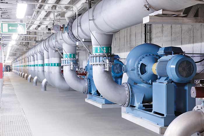
Image 3. Proper grounding is a major factor in preventing bearing damage due to circulating currents.

The impedance of a capacitor varies inversely with frequency. High-frequency currents (such as those from a VFD) can flow through paths normally considered to be insulators such as stator slot liners, stator-to-rotor air gap or the grease film between the bearing race and balls.

The key to mitigating these currents is to provide low impedance ground connections or alternate conductive paths to ensure the current is channeled away from the bearings. (2)

common mode voltage for three-phase sinewave voltagescommon mode voltage for three-phase PWM voltages
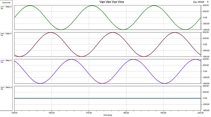
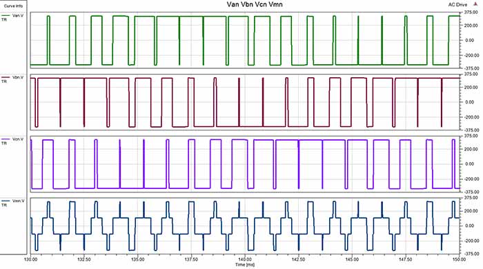
Image 4a (top). Common mode voltage for three-phase sinewave voltages. Image 4b (bottom). Common mode voltage for three-phase PWM voltages.

Image 4 shows four potential paths for high-frequency currents caused by inverter usage. The path in red is a capacitively coupled current from the stator to the rotor through the air gap, with a return path through the motor bearings and ultimately to the drive ground. Current may flow through the motor bearing if the shaft is bonded to the frame (through bearing ball contact) at the instant the dV/dt transition occurs in the CMV.

Discharge current may flow if the bearing first acts as an insulator, then becomes a conductor (due to ball spacing or grease film thickness combinations). Discharge current may also flow if the voltage across the bearing grease film exceeds its breakdown voltage.

The green current path is also due to capacitive coupling between the stator and rotor (across the air gap). In this case, the current flows through a conductive coupling, through the load bearing and load ground, ultimately to the drive ground. Discharge current may flow just as with the previously described red path case. Damage to the load bearing and/or coupling may occur.

The stator winding to frame/shaft current is shown in yellow. This current flows through the stator winding insulation (which capacitively conducts at high frequencies) and through the motor frame, the motor bearing, the motor shaft, the conductive coupling, the load bearing, the load ground and finally to the drive ground. Current flowing in this manner can damage both the motor and load bearings as well as the coupling. The preferred path, to prevent bearing damage, is the stator winding to ground path shown in blue.

In this case, no current flows through the motor or load bearings.

Bearing Current Remediation

There are many possible ways to reduce the magnitude and paths of current flow shown in Image 4. For inverter-fed motors, reducing or eliminating the CMV addresses the problem at its source. However, the CMV is a function of the drive design and cannot be addressed on existing applications.

Pumping application
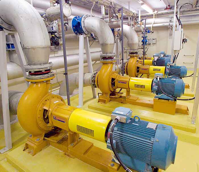
Image 5. Pumping application

For this reason, it is necessary to investigate other means to reduce or eliminate this problem. If multiple current paths are present, multiple remediation methods may be required.

Methods that have proven results include:

  • improving the high-frequency ground connection from the motor to the drive and from the motor to the driven equipment
  • insulating the bearing on the opposite drive end (ODE) of the motor
  • using two insulated motor bearings
  • using a shaft grounding brush across the drive end (DE) motor bearing, which could be mounted inside the motor housing or outside

An important ground path is the connection between the motor and inverter. Cables that provide continuous, low resistivity shielding around the three-phase conductors should be used. The termination of the cable shield should be made by landing these connections on a ground surface free of paint at both the drive ground bus and at the motor frame.

paths of common mode currents from stator to ground, back to drivepaths of common mode currents from stator to ground, back to drive through the cable shield
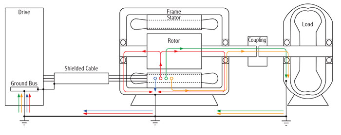
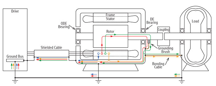
Image 6a (top). Paths of common mode currents from stator to ground, back to drive. Image 6b (bottom). Paths of common mode currents from stator to ground, back to drive through the cable shield.

It is also important to properly ground the frame of the motor. Stator winding to frame currents has the highest potential magnitude of all capacitively coupled currents discussed. Low impedance ground straps should be used to bond the motor frame to the driven equipment frame. A combination of solutions that reduces or eliminates all paths of bearing current flow is shown in Image 6, where most these high-frequency currents will return to the drive through the motor cable shield and little will return to the drive through the building ground.

As shown, an ODE insulated bearing is used with a shaft grounding brush on the drive end. Good high-frequency bonding (such as a flat-braided cable) is used between the motor and load. The insulated ODE bearing prevents potential current flow through it. The shaft brush provides a lower impedance path around the DE bearing. The bonding cable between the motor and load creates a lower impedance path around the bearings in the load.

Conclusion

Bearing currents have existed since the induction motor was invented. CMV induced currents are a phenomenon resulting from high switching frequency drives. Proper grounding is a major factor in preventing bearing damage due to circulating currents. Protecting an installation from bearing current damage requires a thorough understanding of the inverter/motor/load system. Identification of potential high-frequency current paths is crucial to providing an effective solution.

References

  1. C. Pearce, “Bearings Currents - Their Origin and Prevention,” The Electric Journal, August 1927.
  2. R. F. Schiferl &. M. J. Melfi, “Bearing Current Remediation Options,” IEEE Industry Applications Magazine, August 2004.

Issue