Variable frequency drives (VFDs) are everywhere in modern life—operating the fan in home air conditioners, controlling
the pump in the backyard pool or operating submersible pumps in the lift station in the neighborhood, to name a few. As the presence of VFDs grows in our society, so does the sophistication of the control algorithms governing their output. This article will describe the common control types for VFDs and the criteria to consider when selecting a control type for an application.
Control Mode Pros & Cons
Each method of controlling the voltage and current output of the drive has its advantages and disadvantages. Drives configured in volts per hertz (V/Hz) mode require fewer steps to commission than other control options but provide the lowest level of performance. On the other hand, flux vector mode provides better torque characteristics at low speed but requires more steps to commission. Vector (or sensorless vector) control offers the highest level of performance at a higher cost. To achieve the best results, it is essential to consider the application’s criteria before selecting a VFD-control method, rather than choosing the default or easier method to commission the drive.
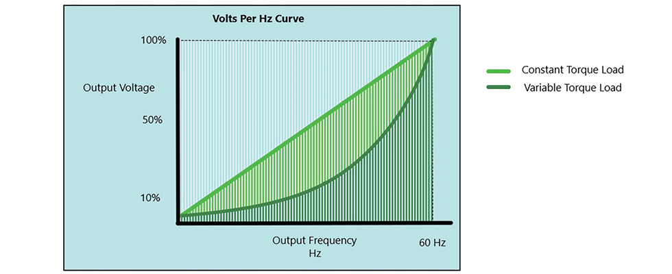
volts per hertz curve (Images courtesy of Mitsubishi Electric)
Most pump and drive fans default to V/Hz mode out of the box. V/Hz mode is best used for “shaft turner” applications—applications that require simple setup and operation—and additional voltage control methods are rarely necessary. Just enter the motor rated current and base frequency, then configure the speed reference, and the drive is ready to run.
In V/Hz mode, the drive output voltage follows a pattern where the voltage is relative to the output frequency. The drive follows this pattern until it reaches the motor base frequency. In North America, this is usually 60 Hz; however, imported or special-purpose motors may have a different base frequency. Fan and pump drives are preconfigured with a V/Hz pattern that is optimized for variable torque loads (torque varies with motor speed), such as centrifugal pumps or fans. A general-purpose drive will default to a V/Hz pattern that better fits a constant torque load (torque does not vary due to motor speed), such as positive displacement pumps, conveyors or rolls. However, V/Hz mode cannot be used with permanent magnet or synchronous reluctance motors.
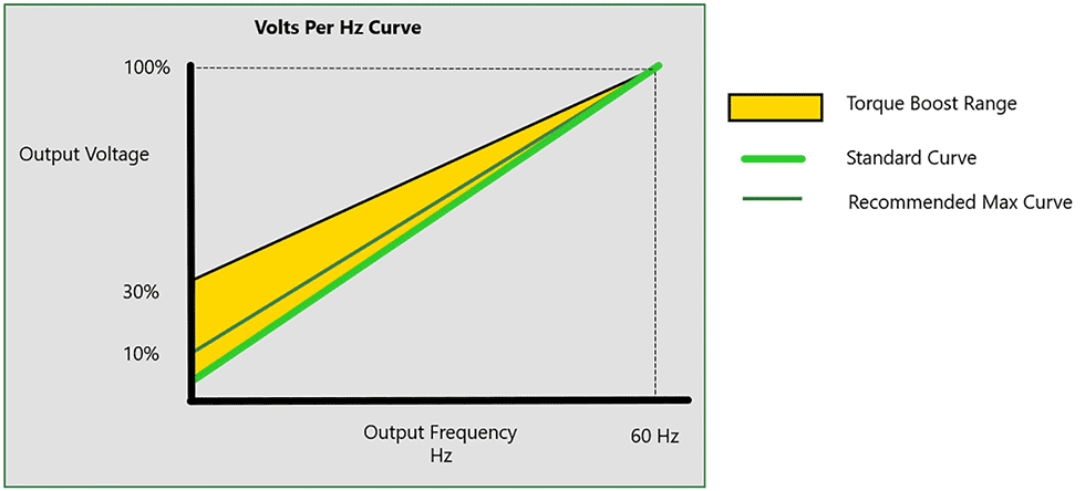
hertz curve with torque boost range
Challenges of Default Settings
While default settings may be convenient and require fewer steps to commission, there are challenges to consider. The downside of V/Hz control is poor torque output at low speed. For some pump designs, applying larger torque at low, or no, speed to overcome static friction of seals and bearings is critical to prevent motor stalling when starting. Most VFDs have a feature labeled “torque boost” or something similar. These features increase output voltage at low output frequencies.
The net result for a motor with heavy load at startup is a larger torque being developed by the motor without a large increase in output current. Torque boosts compensate for voltage drop caused by the motor primary winding and motor leads, creating a larger motor torque. This increase in torque reduces the motor slip (synchronous motor speed vs. actual motor speed) and reduces current used by the motor.
However, if the motor starts with a light load or torque boost is set too high, current increases, and an overcurrent protection function could be triggered. Properly configuring this parameter during commissioning is key to avoiding nuisance VFD trips.
Another potential issue with the V/Hz control method is undetected motor instability or stalling. The voltage relative to frequency is controlled in this mode of operation. Current relative to voltage is not. The drive cannot estimate the actual motor speed, so it is possible for the motor to stall or operate erratically. Some drives have a stall prevention feature that automatically changes output frequency to prevent the inverter from faulting due to overvoltage or overcurrent conditions.
Flux Vector Control
VFDs designed specifically for pumping applications are typically supplied with V/Hz and a version of flux vector control. While vector control of motors can be accomplished with encoder feedback, modern VFDs can operate in flux vector control without physical feedback. Flux vector control methods supply tighter speed regulation than V/Hz modes.
At its core, flux vector control is based on the V/Hz pattern. Additional logic in the drive identifies magnetic flux and torque-producing currents in the motor. Using this information, the drive can control both voltage and current output to the motor. A straight V/Hz control method only controls voltage. Specifically, the drive controls the magnitude and angle between output voltage and current. The net result is a more dynamic response to load changes by the drive, and more accurate speed control.
To utilize flux vector control, the drive requires more motor data than V/Hz mode. Most manufacturers provide either a static and/or rotary auto-tuning routine to determine motor characteristics. When performing a static auto-tuning routine, the drive will apply current to the motor windings and infer motor characteristics. During the test, the motor shaft does not move. A rotary or dynamic auto-tune routine will perform similarly but while rotating the motor. Most VFDs require the motor to be unloaded for a dynamic auto-tune process. Utilizing flux vector control is often an optimum control method for pumping applications, with a good balance between cost and features.
Sensorless Vector Drives
Most VFDs engineered for pumping applications produce less peak torque than general-purpose drives. A typical pumping application rarely requires more than 150% of the drive’s continuous current to generate enough torque to overcome the static friction of the system. However, there are applications with positive displacement pumps and other constant torque loads that benefit from a higher intermittent torque capacity. Drives with higher overload capacities also offer more capable control methods than V/Hz or flux vector.
Sensorless vector control methods provide a quicker response to changes in load and improved torque characteristics. A sensorless vector drive infers motor speed by monitoring current. The drive uses the motor characteristics identified during auto tuning to build a virtual model of the motor. Then, the actual voltage and current are compared to the model values. Because motor command speed and actual speed are known to the drive, it can adjust its output to control speed and torque more accurately. Some sensorless vector drives can produce peak torque at command frequencies as low as 0.3 Hz. This is key for starting when the motor is loaded. This control method can be used to operate permanent magnet and synchronous reluctance motors. Using a drive in sensorless vector mode increases performance. However, these drives are often more expensive and more complex to commission than drives optimized for pumping applications.
Adding an Encoder
Vector control requires a sensor, like an encoder, to provide the motor speed input to the drive control loops and to calculate slip. In vector mode, with a physical speed feedback device like an encoder, full torque is possible at zero speed. For most vector-capable drives, an additional card is required to incorporate the motor encoder. Care must be taken to ensure the encoder is compatible with the VFD. Adding an encoder to the motor adds complexity to the pumping system. Often, electrical noise issues caused by improperly installed encoder wiring can cause faults that are difficult to identify and rectify.
When commissioning a pumping application, selecting the correct control mode is critical to the performance and
life of the system. If the path of least resistance is used to commission VFDs, the system may underperform. By selecting
the appropriate control mode, issues like motor stalling, nuisance overload trips and high energy usage can be avoided. Determining the appropriate control method for a pumping application
requires cost, complexity and performance to be considered.
For more on VFDs, visit pumpsandsystems.com/tags/vfd.