
The gravity flow occurring due to height differs from the flow that achieves its height by pumping.
The exit flow rate of gravity discharge depends on the hydrostatic head displacement occurring via the exit nozzle of the taller standstill position vessel into a recipient nozzle of the lower position vessel, both of which are held at atmospheric pressure, subtracting permanent hydrodynamic head losses occurring in the connected piping and fittings.
Recognizing the net hydrostatic head displacement available and actually occurring (depending on external transitory piping layout as horizontal and/or vertical piping to realize prevailing flow velocity of displacing at the respective cross sections), the pipe sizes of transitory runs and of final exit to acknowledge if the flow-flux occupies the full pipe-flow, layout at the junction of horizontal transitory pipe in plumb with the exiting vertical pipe-run, fittings used as long-radius or standard affecting the minor losses. These all collectively and individually as the situation may have, affect the flow-velocity and cross section of the flow rate exiting the final pipe-run. Recognize them to estimate reasonable gravity discharge from the taller vessel into the lower position vessel if not by field measuring where accuracy matters.
In this scenario, gravity flow rate is the conversion of the hydrostatic head-drop from the standstill water surface at the top of the tall vessel (silo) while draining into another end-of-the-pipe vessel below both held at atmospheric pressure. The piping layout affects the final flow velocity, and it therefore also affects the flow rate exiting into the end-of-the pipe vessel from the full silo with no fresh inflow into it.
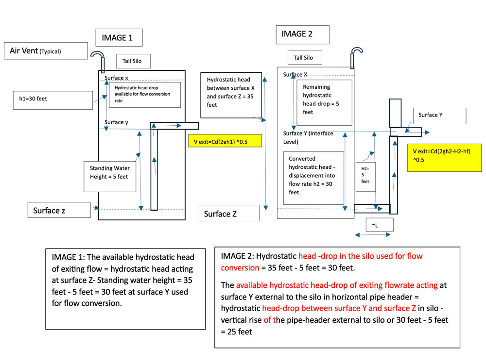
IMAGE 2: Hydrostatic head-drop in the silo used for flow conversion = 35 feet - 5 feet = 30 feet. The available hydrostatic head-drop of exiting flow rate acting at surface Y external to the silo in horizontal pipe header = hydrostatic head-drop between surface Y and surface Z in silo - vertical rise of the pipe header external to silo or 30 feet - 5 feet = 25 feet
The Exit Nozzle & Standstill Position of the Water Surface
The exit flow velocity is the conversion of the hydrostatic head-drop from the standstill position of water surface X to the exit nozzle from the silo at surface Y in Image 1. In the case of Image 2, however, the causation of flow rate is due to hydrostatic head displacement from interface surface Y in the silo to the water surface Y in the 2-inch Փ (diameter) external horizontal pipe header via the exiting nozzle surface Z in the bottom of the silo. The remaining unconverted hydrostatic head-drop into flow velocity is between the depleting water surface X and surface Y in the silo in this case. This remaining delta hydrostatic head-drop is available for conversion into flow velocity in the downstream 4-inch Փ piping system by virtue of the silo exit at water surface Z at the bottom. This remaining delta hydrostatic head-drop decreases as the water surface drops in the silo upon draining into the end-of-the-pipe vessel.
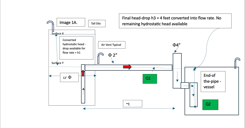
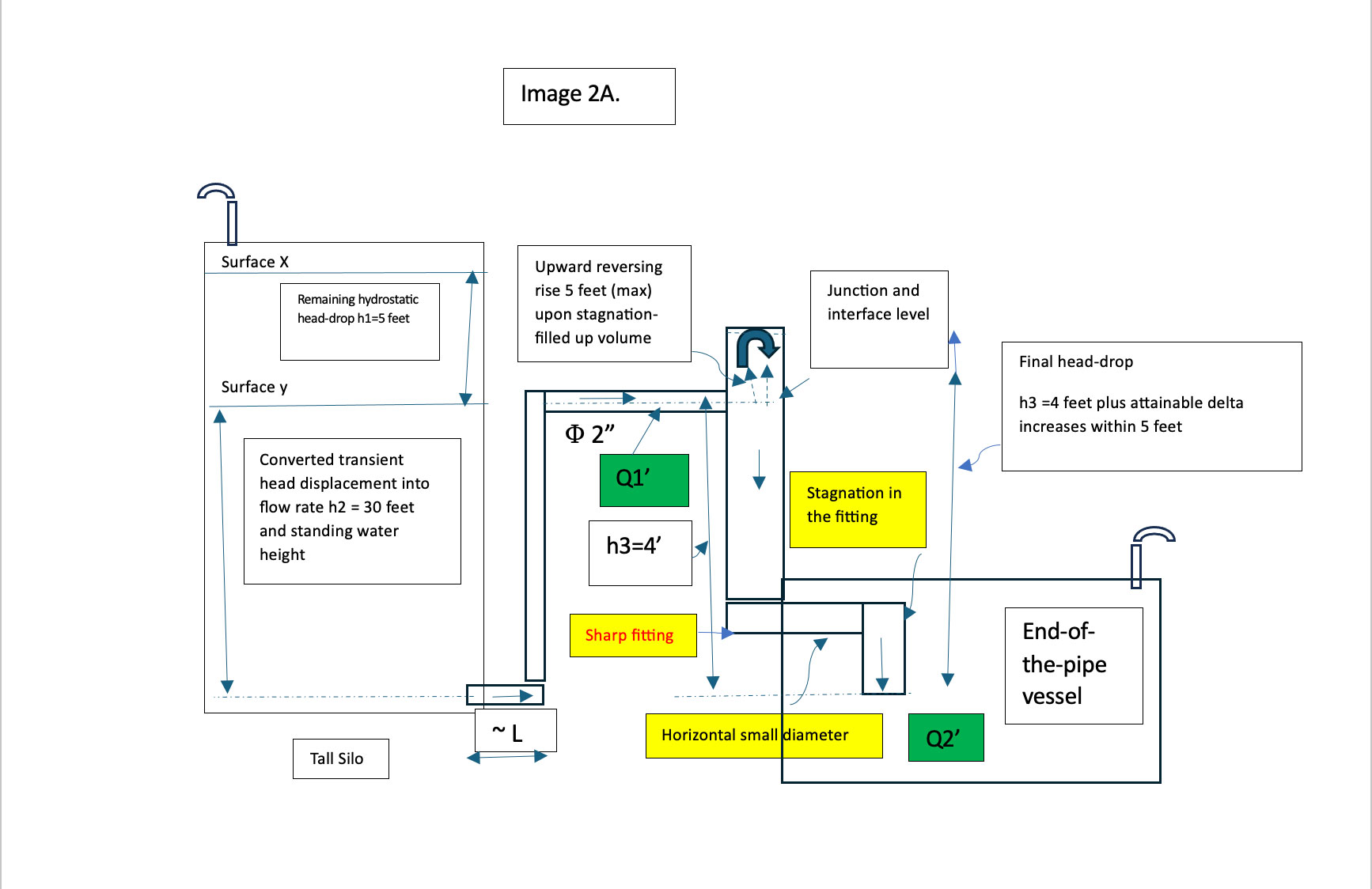
The permanent dynamic frictional head losses in both the piping systems, including pressure drop in the throttled valve (not shown in Images 1A and 2A), are subtracted from the hydrostatic head-drop that is converted into flow velocity (hydrostatic head-drop from water surface X and water surface Y in the silo in Image 1 and from hydrostatic head-drop from interface water surface Y in the silo to the water surface in the 2-inch Փ external pipe-header in Image 2). This is done to derive the horizontal flow velocity of the entrance in the junction of 2-inch Փ horizontal header-pipe laid out at elevation Y before dropping into the 4-inch diameter header leading to the end-of-the-pipe-vessel. Because the pipe-header runs external to the silo in Image 2 or Image 2A, the hydrostatic head-drop converted into flow rate needs to include reduction due to the additional travel height of the 2-inch Փ riser pipe. This is not the case with downcomer pipe submerged below the water’s surface in the case of the layout in Image 1 or 1A.
Also, the remaining hydrostatic head-drop in the silo in the case of Image 2 or 2A has the potential to reflect as the delta rise of the water column in the 4-inch Փ vertical pipe due to a release of back-pressure from the silo (above the junction of the 2-inch horizontal pipe-header in plumb with the 4-inch Փ vertical pipe-header as per Image 2A; total drop of attainable delta increases by 5 feet) upon reaching momentary flow stagnation in the downstream sharp fitting of the piping system, thus increasing terminal velocity of fall below into the end-of-the-pipe-vessel.
Note that in Image 2 and 2A, the exit nozzle is flush with the wall of the silo and not penetrating.
Gravity Flow Rate vs. Pumped Flow Rate
The downward gravity flow rate measured at the given location in the external pipe-header varies as per the product of the net position drop of the water surface between the silo and external discharge pipe-header converted into flow velocity and flow cross section per the diameter of the pipe laid below the position of the water’s surface. On the other end, the pumped (pressurized) flow rate in the single pipe-header system is consistent. This is because the sizing of the pump does not vary with the size of the transitory pipe runs.
Larger pipe size increases the discharge rate in the case of gravity flow, while the pumped flow slows down in the pipe enlargement while maintaining consistent discharge.
The pumped (pressurized) flow rate occupies the full cross section of the pipe, whereas the quantity of the water-volume collectable in the liquid-volume of the passageway decides the cross section of the fluid flow in the pipe in case of gravity flow rate.
The flow rate of gravity discharge exiting from the silo and entering the junction of a 2-inch Փ horizontal header with a 4-inch Փ vertical header will reduce due to the piping layout shown in Image 2A rather than the piping layout in Image 1A. This is due to the energy consumed in overcoming the additional height of water displacement required from exit from the silo at surface Z to surface Y external to the silo.
Final Notes
Note that the hydrostatic head-drop between surface X and surface Y as per the piping layout in Image 2A is not converted into flow velocity but remains in the exiting fluid from surface Z from the silo. This remaining hydrostatic head-drop has the potential to interact again if the flow must reach momentary flow stagnation in the downstream piping fitting of the system.
Pumped discharge flow rate is consistent and does not vary with the pipe diameter, unlike horizontal gravity flow, which varies depending on the cross section of flow at the location of measurement. In other words, the horizontal gravity flow rate increases in the pipe enlargement and reduces in the pipe contraction.
