
The rise in total generation capacity of renewable energy sources such as wind and solar is resulting in traditional base load coal generation plants being more frequently used to follow fluctuating electricity demand, also called peak load operating. This change in operation has an effect on the power plant equipment, since machines are now subjected to operating conditions they were not originally designed for. The term base load is used to mean a plant operating at a stable electrical output for a sustained period of time. This is typically at or near the peak efficiency of the plant. What this means for the boiler water circulating pump (BWCP) in the plant is there are minimal thermal cycles and, hence, minimal cyclic thermal stresses. The equipment can be operated at a stable, constant condition rather than frequently being started and stopped or ramped up and down the pump curves. In contrast, the terms peak following or peak load mean operation that fluctuates up or down to match the short-term electrical grid power demand. This plant cycling means the BWCPs experience increased thermal cycling and either starts and stops or fluctuating operation along the pump curve as the plant flexes to provide a changing electrical demand. The fluctuation of boiler evaporation rate and, in some cases, boiler pressure has an effect on the operation of the BWCP. The BWCP is typically used in forced circulation drum boilers to provide the necessary head (pressure) to overcome the frictional losses encountered in the boiler tubes. This allows the water circulating through the boiler to be turned into steam to generate electrical power in the turbine-generator set.
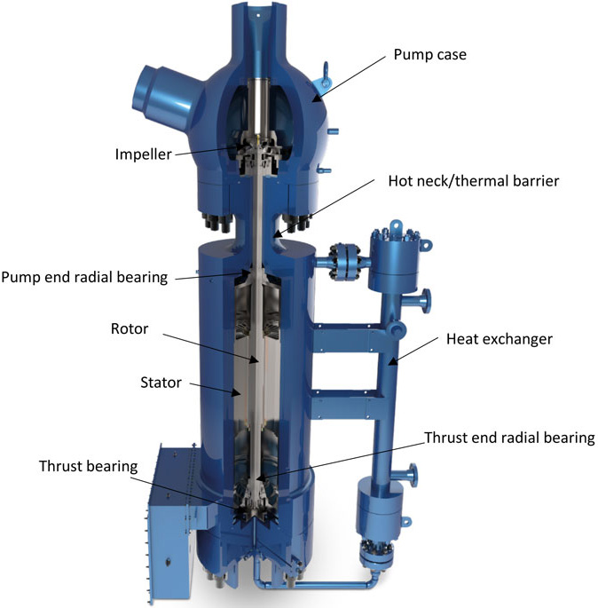 Image 1. Typical BWCP (Images courtesy of Hayward Tyler)
Thrust Bearing
A typical BWCP is supported axially using a hydrodynamic thrust bearing. The bearing uses a water wedge formed between the thrust disc, which is keyed to the shaft, and tilting thrust pads. The thrust bearing accommodates the weight of the rotor and additional thrust loads from the pump including a suitable design safety factor. When the motor starts up, the hydraulic lift from the impeller lifts the rotating assembly upwards to establish a film of water between the thrust bearing surfaces during stable operation. When the BWCP is shut off, the rotor loses the hydraulic lift and returns down to the reverse thrust bearing. Initially during startup there is insufficient fluid film between the nonmetallic bearing and the thrust pads, so the friction between the pads can cause a small amount of material wear. This reduces the thickness of the bearing material and begins to open up the distance the rotor can travel (rotor end float). This means the rotor is traveling farther every time the motor is de-energized, resulting in a larger thrust. Long-term cycling can result in damage to the thrust bearing that requires accelerated maintenance or—in some cases—catastrophic failure of the thrust bearing requiring extensive repairs. Thrust inspections are recommended every three years. Users should then develop an asset management strategy based on the as-found condition of the thrust bearing components. Monitoring pump performance and critical clearances, as found during inspections, allows users to better understand the wear associated with their plant running regime and adjust maintenance cycles (as far as reasonably practical) to maximize the life of the BWCP.Radial Bearings
Similarly to the thrust, the radial bearings in the BWCP use hydrodynamic bearings. The radial bearings are at the thrust end and pump end. Accurate alignment of the radial bearing is controlled by manufacturing tolerances of the stator housing and motor case. The radial bearings are sized to absorb loads from unbalanced magnetic pull (UMP) on the rotor and hydraulic fluctuations in the pump creating unbalanced loads and safe rotor dynamic characteristics. When the BWCP starts there is insufficient fluid film between the journal sleeve and the bearing surface. This creates wear on the pads resulting in lost material and larger clearances. The bearing wear allows the rotor to deviate from the center axis of the stator, which increases the UMP, in turn increasing bearing wear. This allows the rotor to deviate from alignment with the stator, then the damage propagates due to worn radial bearings. If the bearing clearances become excessive under extreme conditions, during startup the UMP could cause rotor-to-stator contact due to bending in the rotor, which could damage the stator and rotor lamination packs, resulting in the need for restacking.Impeller Wear Ring
The impeller wear ring is set with a predetermined diametrical clearance to the pump case or diffuser wear ring to control the pressure drop across the surface and the amount of fluid recirculated. The distance from the pump case to motor case mating face and end of the impeller (known as the “A” dimension) is controlled to ensure no axial contact. In scenarios where the plant is quickly changing load or fully starting and stopping, the motor is typically at a different temperature than the pump case and rotating assembly. Depending on that temperature differential, the impeller and pump case will grow or shrink at different rates. This reduces the wear ring clearance and can cause contact. In severe situations, binding of the rotating assembly to the static wear ring can occur. Frequent load changes will cause accelerated degradation to the wear rings. This increases the clearance and reduces efficiency but more severely shortens the life of the wear rings and can cause major damage to the impeller and rotating assembly. Excessive contact of the impeller-to-pump case can bend the rotor, damage the radial bearings and damage the stator windings due to debris being circulated through the motor.Pump Case
The pump case on a BWCP is welded into the pipework and typically made from a thick-walled carbon steel casting. Frequent thermal cycling on the pump case due to changing operating loads subjects the pump case to thermal stresses as the pump case tries to expand freely yet is constrained by the pipework and connection to the motor. Frequent thermal stress cycling can present problems with fatigue crack development at critical regions such as thicknesses, nozzle regions and welds. Operators should inspect pump cases for the development and propagation of cracking. If the pump case welds are not part of a maintenance program associated with “high energy pipework” they should be included in the periodic inspection of the pump case.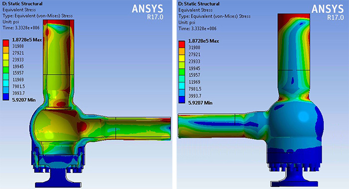 Image 2. Thermal stresses on pump case from fluid or metal differential temperatures
.jpg) Image 3. Cracks in a BWCP pump case
Image 3. Cracks in a BWCP pump caseElectrical Motor
The electrical motor is under the most stress during a startup. The in-rush current of a typical BWCP is approximately four-and-a-half to five times the full load current. The majority of BWCPs are wet stator units (WSU), which means the rotor and stator are submerged in water. WSUs use a cross-linked polyethylene (XLPE) insulating material to insulate the copper wire from the water in the stator. This current causes the copper wire to heat up, creating a short-term negative effect on the insulation. Every time a motor is started, it reduces the lifetime of the insulation, leading to increased risk of an insulation failure. When the stator is initially wound, the cable in the slots are wedged together to keep them packed tightly. With normal operation of the electrical motor, the cable in the slots bunch together and pull to the outside of the stator from the magnetic forces in the motor. This can loosen cable in the stator slots allowing additional cable movement. During startup of the motor, the cable in the end turn phases exerts magnetic forces on cables in adjacent end turn phases causing the end turns to move and vibrate. The outer coils are pushed toward the outside of the stator shell and the inner coils are pulled toward the rotor. The end turns flex with the changing magnetic fields induced by incoming current.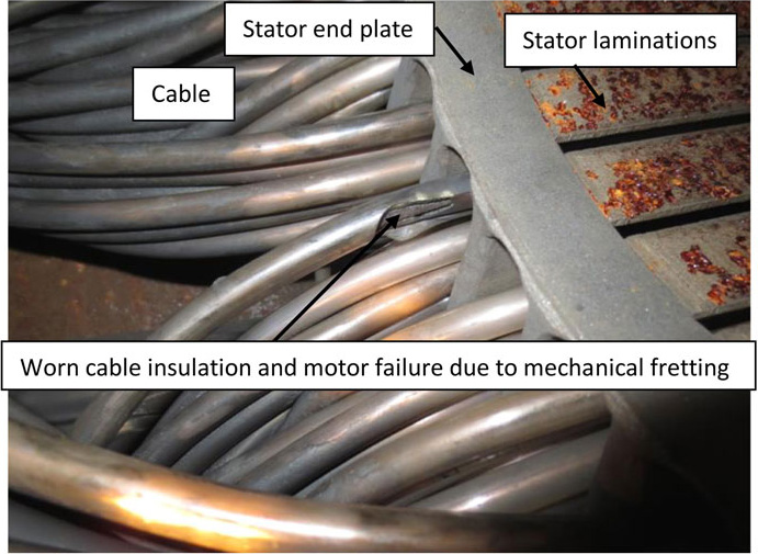 Image 4. This shows failure to ground due to mechanical fretting and insulation wear.
UMP
UMP occurs when the centerline of the rotor does not line up with the centerline of the stator. Upon startup, the electric motor acts like a magnet, pulling the rotor approximately in the direction of the smallest air gap. This can cause a static or dynamic eccentricity in the rotor motion. As mentioned previously, under extreme conditions with sufficient bearing wear there could be rotor-to-stator contact.Insufficient NPSHa
During fluctuating plant load (MW) or unplanned shutdowns some have observed that the BWCP can experience cavitation. This can be caused by a few different scenarios. First, the net positive suction head available (NPSHa) could have decreased because the steam drum is vented or the drum pressure is lower than normal. In this scenario the pressure on the liquid surface in the drum is reduced. This means that the only NPSHa to the pump is the static elevation of the liquid above the pump minus any frictional losses. This is insufficient, causing cavitation at the pump suction. Second, the system resistance—which consists of the static elevation pumped plus the resistance of pipe fittings, valves etc.—could have decreased. The pump will increase flow until its developed head intersects with the new system resistance curve. As net positive suction head required (NPSHr) rises with flow there may not be enough NPSHa to satisfy NPSHr. Third, the BWCPs are used to help force-cool the boiler in the event of a tube leak. As the pressure and temperature in the boiler are reduced to repair, the tube leak the BWCPs are left running to force additional flow through the boiler. This results in a drop in NPSHa, which may fall below NPSHr. If cavitation occurs it will likely cause damage to the main and reverse thrust bearing from loss of hydraulic lift in the impeller as a consequence of vapor entering the suction. This can cause the rotating assembly to shuttle between bearings faces causing damage. It will also likely damage the impeller, which sounds like marbles pumped through the impeller and can cause pitting on the surface as the bubbles collapse. More commonly, damage is attributed to increased vibration resulting in increased wear on the radial and thrust bearings.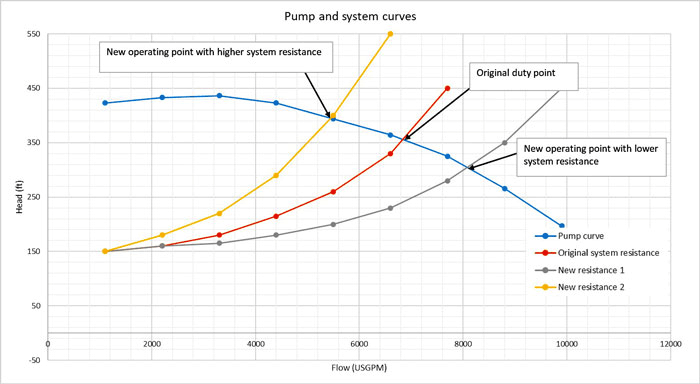 Image 5. Pump curve and various system resistance curves