
Many industries use variable frequency drives (VFDs) with induction motors. Introduced in the 1960s, VFD technology has advanced considerably during the past 50 years. The engineering advancements have encouraged operators to consider other factors during particular applications, such as harmonics, energy efficiency, temperature, rise time, cable length and switching length. Facilities that want to include VFDs often face problems during their installation. One of the most common issues associated with VFD installations is stray current, or shaft current, caused by common-mode voltage. Approximately 41 percent of the total failures in motors are the result of bearing currents. The primary cause is unbalanced current distribution with VFDs.
What Is Common-Mode Voltage?
The VFD inverter supplies unbalanced three-phase voltage to the motor. Common-mode voltages are coupled to the rotor through parasitic capacitances between the stator winding and rotor. This high-frequency voltage may result in excessive common-mode currents. Existing stray capacitances between the motor and ground may allow current to flow to the ground, passing through the rotor, shaft and bearings and reaching the grounded end shield.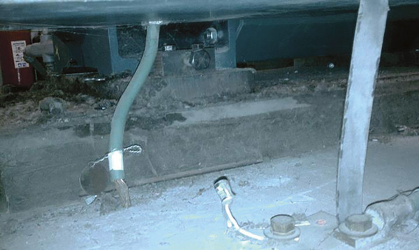 Ground cables can solve many problems associated with stray currents traveling through motors. However, they must be properly maintained. (Article images courtesy of WEG Electric Corp.)
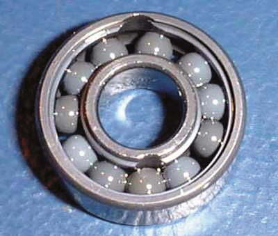 The rollers in a ceramic bearing are effective electrical insulators.
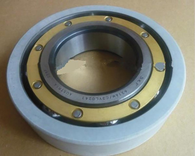 Despite being a reliable insulator, a coated bearing may fail to stop stray currents if the coating is scratched or damaged.
Stray Currents and Their Paths
Stray currents are typically seen in larger motors—above 444T—and poorly grounded systems, though they have been observed in all sizes of motors and applications. The current has several options when traveling to the ground, either through the motor bearings or other equipment bearings. This means that the motor does not always fail.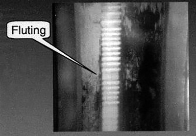
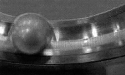 Discharge currents erode the bearings over time, leading to furrows or fluting.
- Stator-to-frame capacitive currents result from higher frequencies caused by switching. The appropriate solution is to incorporate VFD cable and low-impedance grounding straps.
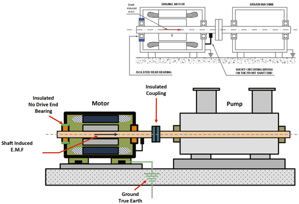
- Stator-to-rotor capacitive currents are created in the rotor. The currents look for a path back to the VFD, and the driven equipment (for example, the pump) or the motor bearings offer the least resistance. Installing a shaft grounding brush provides a low-impedance return path to the VFD.
- Motor circulating currents are created by asymmetry in the magnetic field axially along the motor rotor. Insulated opposite drive-end bearing and drive-end shaft grounding brush minimize the risk of these currents forming, as does a low-impedance return path to the VFD. Insulated opposite drive-end bearings are typically recommended for motors more than 150 horsepower (447T and larger). Some industrial end users require insulated bearings on all VFD systems, even in lower-horsepower applications.
 Directing the current to the ground includes two processes: grounding the motor to the primary baseplate and grounding the baseplate to the ground.
- Insulated housings place a layer of insulation between the bearing housing, fit and the rest of the end bell.
- Ceramic bearings use standard steel inner and outer rings. The rolling elements are made of silicon nitride, providing excellent insulating properties.
- Coated bearings consist of an outer or inner ring, plasma-sprayed with a coating of aluminum oxide and then resin-sealed. The downside of this technology is that the coating is thin. If scratched or damaged, the bearing may not protect the motor from stray currents.
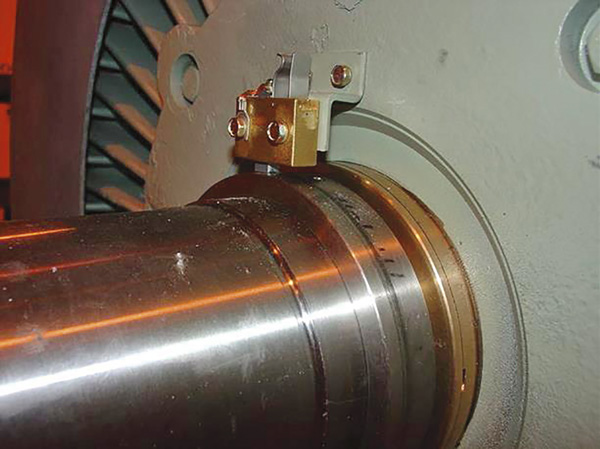 Installing a shaft grounding brush provides a low-impedance return path to the VFD.
Grounding
Directing the current to the ground includes two processes: grounding the motor to the primary baseplate and grounding the baseplate to the ground.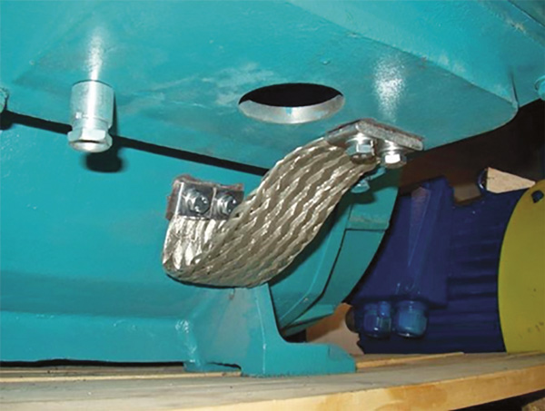 Low-impedance grounding strips are a solution to stator-to-frame capacitive currents, in addition to VFD cables.
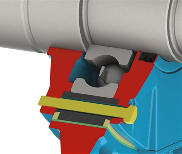 Insulated bearing housings place a layer of insulation between the bearing housing, fit and the rest of the end bell.