
In Europe, it is estimated that around 10 percent of electrical power is used for pumping equipment1, which is a significant part of running a manufacturing operation. One of the consequences of this usage is that regulatory bodies in the United Kingdom and plant owners are focusing on improving the energy efficiency of pumps and pumping systems. Appropriate selection of mechanical sealing systems can have a significant impact on a plant’s energy efficiency.
Mechanical Seals
The purpose of mechanical seals is to seal the process fluid. Whether the fluid is toxic or expensive, the objective of these seals is to keep it within the system and pipework to prevent it from seeping out. If the liquid or process fluid that is leaking is heated, the system is losing costly energy. So whether a system involves flanges, valve stems or pump seals, it is necessary to think of the seal not only as preventing process fluid contamination and leakage to external atmosphere, but also as an important part of conserving energy within the system. With relatively small seals, about 1 to 2 inches (25 to 50 millimeters [mm]) in diameter, energy consumption is relatively low at 1 horsepower (hp), or 0.75 kilowatts (kW), as a maximum.2 Larger sealing mechanisms can consume more than 3 hp (2.24 kW) as a maximum power absorption. This number may seem low, but if the focus is on the thermal inefficiency of seal flush plans, the energy that may be lost in inefficient systems can be significant. To function correctly, mechanical seals need to be flushed with a fluid to lubricate and keep the seal faces cool. This is accomplished through the use of sealing systems and various configurations of seal flush plans (American Petroleum Institute [API] plans). Mechanical seals on pumps are among the most delicate components. Seal flush plans change the environment in which the seals operate, helping them flourish and provide reliable operation. In simple terms, flush plans are used to create a stable and idealized environment for the seal, and they are formalized by API in its standard API 682, where they are detailed. The Fluid Sealing Association (FSA) conducted a survey3 of pumps incorporating a total of 28,000 seals where the process temperature exceeded 400 F (204 C). Figure 1 shows the most popular flush plans used and their energy absorption. Flush Plan 32, the second most commonly specified in the survey, is by far the highest energy user.
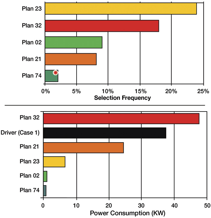 Figure 1. Energy efficiency of popular flush plans (Graphics courtesy of AESSEAL)
Understanding the flush plans is critical for impacting energy efficiency in seal systems and seeing how they control the seal environment. Currently, API 682 Standard is in its 4th edition and details more than 30 plans.4 The standard has evolved over 20 years and serves as a representative sound engineering practice in the application of mechanical seals. The latest edition has incorporated many of the improvements from the previous editions as highlighted by users. Looking at studies on different flush plans undertaken by FSA allows comparison of some plans with a hypothetical case study. The single-seal flush plans are Plans 21, 23, 32 and 62 (see Figures 2 through 5). We will look at dual seals and the appropriate seal flush plans in a separate study. Outlined below are the alternative flush plans for single seals.
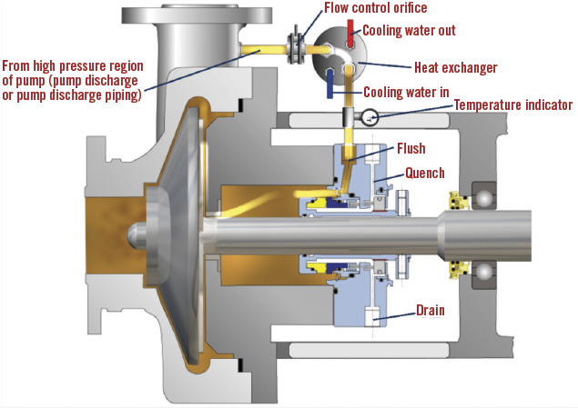 Figure 2. A diagram showing API Plan 21.
API Plan 21: This is commonly used for high-temperature process fluids. API Plan 21 takes a simple side stream from the discharge, which is at higher pressure than the seal chamber. The higher pressure drives the hot liquid through an orifice plate that controls the flow, then through a heat exchanger before this cooler liquid is injected on the seal flush over the seal faces and then fed back into the process—an open-loop cooling system. One issue with API Plan 21 is that the seal flush liquid enters the process and, with the process fluid being at a higher temperature, this additional cool flush liquid dilutes the process.
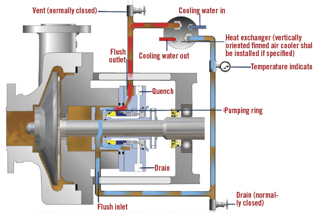 Figure 3. A diagram showing API Plan 23
API Plan 23: By comparison, API Plan 23 can be described as a closed-loop cooling system. It is probably the most efficient way to remove heat from a mechanical seal. The seal chamber is closed down by throat bushing at the neck of the seal chamber, and within the seal chamber is a secondary, small impeller to circulate liquid though the heat exchanger. Plan 23 is significantly more efficient than Plan 21 because only heat from the seal faces and any heat that comes through the pump casing is removed, and no heat is removed from the process.
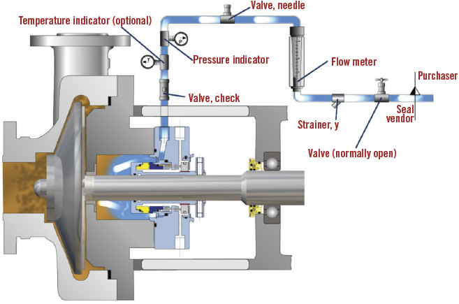 Figure 4. A diagram showing API Plan 32.
API Plan 32: This plan involves injecting a clean, cold liquid from an external source through various controls, through the seal faces and into the process. The flush liquid is generally significantly cooler than the process fluid, and this liquid dilutes the process and has a significant effect on the thermal efficiency of the process. This scenario can be compared to constantly running the cold water in the bath, while trying to keep it warm with the hot tap—the bathwater quickly loses temperature.
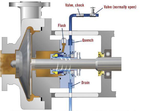 Figure 5. A diagram showing API Plan 62
API Plan 62: API Plan 62 is an atmospheric plan commonly used on hot-oil-type applications for a single seal. With Plan 62, steam is taken across the atmospheric side of the seal and down to a drain system. The steam is not used for cooling but instead carries away any hydrocarbon particles that congeal on the atmospheric side of the face, removing them before they start carbonizing and causing the seal and faces to “hang up.” Plan 62 is a relatively energy-efficient method of sealing a hot-oil pump. Generally, only a small amount of steam is required; however, controlling the steam flow on a steam quench can be difficult. For example, in some installations the steam escapes to the atmospheric side of the seal, which dramatically increases the energy requirement, quickly making the system inefficient. Most issues with the API Plan 62 steam quench’s energy efficiency are a result of poor maintenance.
Applying the Plans
Applying the previously mentioned API plans to a hypothetical hot-oil pumping application illustrates the relative energy efficiency of each (see Table 1).
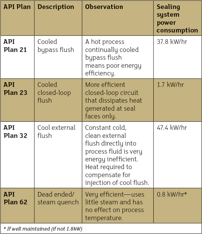 Table 1. A comparison of single-seal flush plans
The configuration of this example application is a single-stage, end-suction centrifugal pump (API 610 compliant), based on the following characteristics and factors. Pumped fluid: Hydrocarbon at 600 F (315 C) Specific gravity: 0.8 Specific heat: 1.67 kJ-C (0.4 BTU/lb-C) System pressure: 345 kPag (50 psig) in seal chamber Pump driver: 50 hp (typical) Sealing devices: Compression packing, mechanical seals Assumptions: Heat lost at the pump must be replaced at the system boiler/heat exchanger To put the figures in Table 1 into context, if a pump is running 24 hours a day, 365 days a year, the difference between flushing a seal using API Plan 32 and API Plan 23 can mean around 400,000 kW of energy saved each year. When these savings, which equate to a 96 percent reduction in energy costs, are spread across multiple pumps and multiple locations, the potential overall savings are huge. Potential sealing system savings can exceed the energy savings obtained from switching to variable frequency drives, improving pump hydraulics, trimming impellers or resizing pumps in many applications. Selection of inappropriate sealing systems can have a significant impact on the thermal efficiency of a plant and a plant’s utilities. Sealing systems found in many industrial applications, even when functioning as intended, are extremely wasteful of energy. However, the sealing industry has technologies that can overcome some of this energy waste, and there is increased awareness about these solutions. Improved sealing technologies available today can reduce the need for energy-wasting systems that result in cooling/dilution of the process and the need for downstream separation/evaporation, re-heating and/or effluent treatment. Being able to choose between different sealing systems or flush plans requires a good understanding of the principles of their operation and why they each are used. The best way to access this knowledge is to work with a sealing partner that has an understanding of this specialized area.
- youtube.com/watch?v=FvPRTowCK-E
- maintenancetechnology.com/2010/01/saving-energy-with-sealing-systems-344/
- pumpsystemsmatter.org/uploadedFiles/Pumps/Membership/Member_Services/Meetings/AZIBERT%20-%20Sealing%20Systems%20Energy%20Efficiency.pdf
- api.org
