
A discussion of current compression packing technology will help set the stage for an example of how this can be accomplished. Compression packing is still widely used to seal rotating equipment such as pumps. The most common type of compression packing used in rotating equipment is braided yarn made from a variety of materials such as graphite, aramid, and PTFE (Polytetraflouroethylene). Many braided packings will also incorporate blocking agents and other coatings to minimize leakage through them and provide cooling and lubrication during startup. The braided packing is cut into rings, inserted into a stuffing box and compressed using a bolted gland. Under axial compression, the packing expands radially, creating a seal between the stationary body of the equipment and the dynamic surface, usually a rotating shaft.
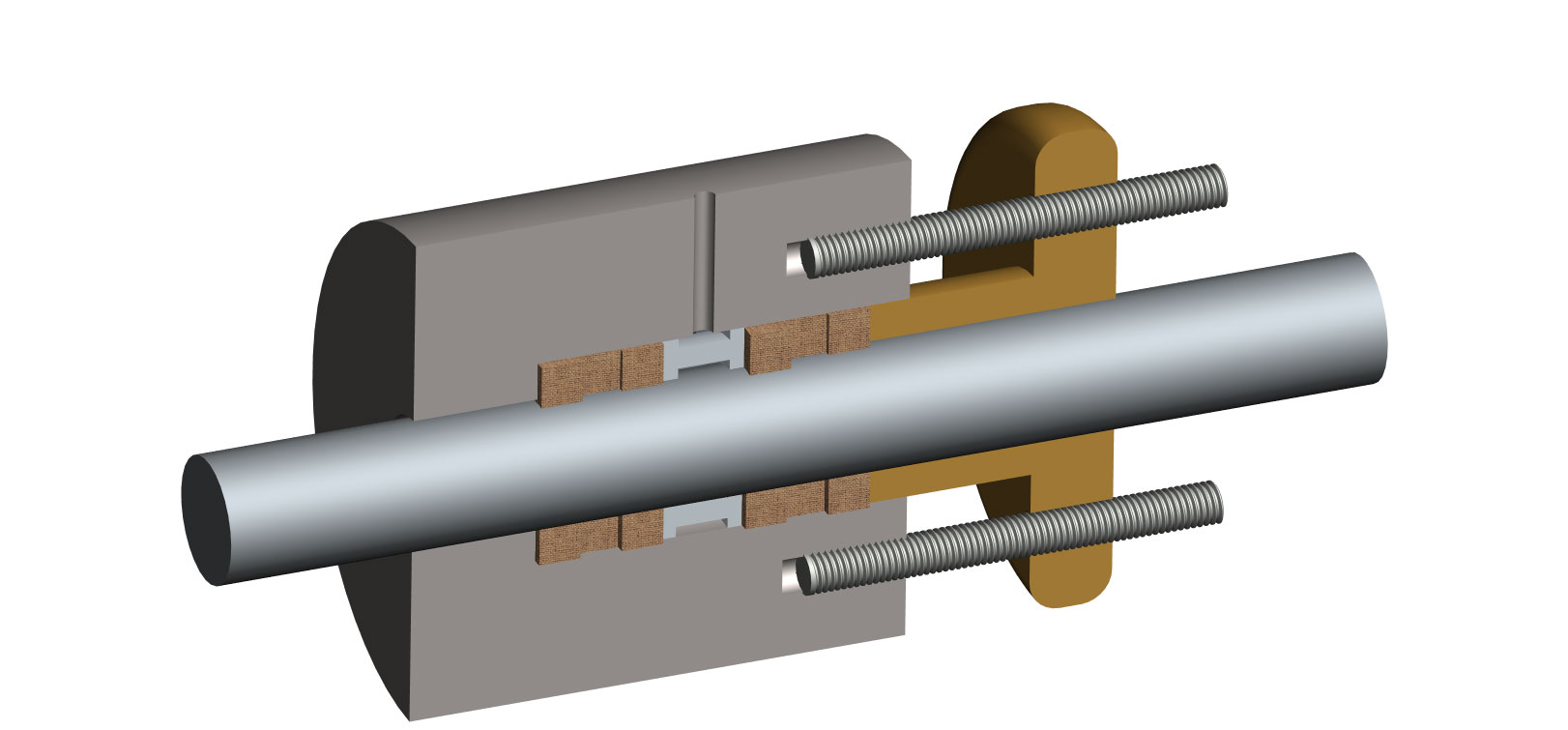 |
Figure 1. Standard packing system |
Performance Factors
There are a myriad of factors that can affect the performance of packing. These include:
Equipment condition and design—stuffing box finish, shaft finish, shaft run-out and concentricity with the stuffing box, number of packing rings, clearances between the shaft, gland and stuffing box.
Application parameters—temperature, pressure, surface speed, and the properties of the media being sealed (i.e., corrosive or abrasive).
Packing properties—thermal conductivity, coefficient of friction, material temperature limits and chemical compatibility, material strength, construction, density and permeability.
With all mechanical packing, some leakage of the sealed fluid is to be expected, but it must be controllable. Friction between the shaft and packing during operation generates heat. The controlled fluid leakage provides some measure of cooling and lubrication which helps manage the heat generation. That is the tradeoff—for a given application, lower leakage rates can translate to higher operating temperatures. Higher leakage rates can yield lower operating temperatures. Lower leakage rates could mean less lost product but shorter packing life and vice versa.
Some established, general guidelines on expected packing leakage can be found in the Third Edition of the FSA/ESA Compression Packing Technical Manual, but end-user experience and/or requirements for a given application and packing type can vary widely. One operator may look to achieve no visible leakage from an application whereas another may be satisfied with 20 milliliters per minute.
Application Guidelines
Compression packing is considered a cost effective sealing solution, particularly in applications with larger shaft diameters for which other sealing options are more costly. The standard packing designs and materials in use today can handle some pretty extreme conditions, i.e. pressures to 500 psi (34 bar), shaft speeds to more than 4,000 feet per minute (more than 20 meters per second) and temperatures to more than 600 degrees F (more than 315 degrees C).
What about the severe service applications with operating parameters beyond these conditions? The example application described in the next section will show that using techniques gained through field experience and laboratory testing can extend the effective sealing capabilities of compression packing to severe service conditions beyond the published limits for the standard packing.
High Pressure Slurry Pumps
In mining operations, there are applications in which ore slurry has to be moved from the mining site to the processing facilities. This is done with pumps in series that develop enough pressure to move this viscous abrasive fluid long distances. The particulates are abrasive and can wear packing fibers, pump shafts and sleeves and increase frictional heat. The elevated pressure creates high compression on the packing that can increase packing friction and wear, cause extrusion of the packing through clearances between the gland and shaft and make controlling leakage difficult. Leakage control can be complicated at these pressures because small adjustments of the gland bolts can cause drastic changes in leak rate and, subsequently, the frictional heat and operating temperature of the packing set.
Often in these harsh applications, the packing is flushed through a lantern ring (See Figure 1.). The introduction of the flush is meant to cool and lubricate the packing and keep particulate from getting between the I.D. of the packing set and the O.D. of the shaft. The flush pressure has to be higher than the stuffing box pressure to ensure a positive flow.
 |
Figure 2. Modified Packing System |
Case Study
So, how can compression packing be applied in this service? Let's look at an example of a slurry pump in an ore transport system. The operating pressure of this particular pump is 650 psi (44 bar) with potential surges to over 700 psi (48 bar). It is flushed with water at a pressure of 670 psi (46 bar). The flush was recycled plant water and contains some particulate. Shaft diameter was 6.25 inches (159 millimeters) rotating at about 600 rpm (980 feet per minute or 5 meters per second); packing cross section was ¾ inch ( 19 millimeters). The stuffing box was packed in a 3/LR/3 configuration (three rings below the lantern ring, three rings above).
Standard Packing
Using a para-aramid reinforced graphite coated PTFE fiber packing, the service life of the application was typically weeks—maybe a month or two. The intent of using this design was to reduce the extrusion of the packing rings by using a material with very strong corner reinforcement. Failure mode was charring of the packing ring I.D. (overheating due to friction), heavy sleeve wear (abrasion) and sometimes a complete loss of a seal (heavy leakage).
Inspection of the packing sets removed from the stuffing box revealed that the high pressure was compressing the packing significantly, which moved the lantern ring out of position relative to the flush port. The flush would then start leaking past the packing O.D. in roughly the same location as the flush injection port, thus reducing the cooling and lubrication of the dynamic sealing surface.
Laboratory Tests Point to a Solution
Laboratory testing confirmed leakage control with the standard packing rings and configuration was extremely difficult. Leakage dropped to zero at startup and the packing set quickly overheated. After a number of tests, the packing system shown in Figure 2 yielded consistently positive results—tolerable leakage and temperature control from startup. This system incorporated the same para-aramid reinforced graphite coated PTFE packing with dimensional changes and system component enhancements.
The solution used a close-tolerance bushing with an integral lantern ring in place of the old lantern ring and two packing rings instead six. These served a number of purposes, Specifically, they:
Helped create a pressure drop to reduce the effective pressure that the packing set is sealing
Reduced extrusion clearances for the packing
Ensured that as the packing is properly compressed, the flush port is always kept clear and the flush is distributed to the full circumference of the packing set I.D.
To avoid possible clogging of the restriction bushing with particulate, steps should be taken to remove or minimize the particulate content in the fluid entering the packing set. This can be done either by filtering or screening the flush fluid prior to use or with other solids separation technologies.
Packing Configuration
The packing rings were cut differently than is standard for butt cut rings (90 degrees to the packing axis). They were cut slightly shorter than nominal by 1/8” (3 millimeters). This left a slight gap in each ring when inserted into the stuffing box, ensuring there was an effective leak path for the flush fluid to get through the packing set. The use of two rings seems counterintuitive but in laboratory testing with the extra ring gap, the leakage was controllable at startup and stayed consistent during longer term operation. This configuration has since been considered for standardization based on these results.
The standard packing selected and used in the application had a maximum recommended pressure rating well below the application pressures. The packing material has low tensile strength but good resistance to thermal fluctuations and gland adjustments. The modifications to the packing dimensional configuration and stuffing box resolved the performance problems by reducing the severity of the conditions under which the packing set operated.
Conclusion
Similar types of modifications have been successfully used in applications that operate at very high speeds. Altering the conditions at the seal can make the difference between a maintenance headache and a consistently good performing sealing solution for severe service applications.
Contact your sealing system manufacturer if you have a severe service application. They will have the experience with compression packing in a broad range of applications and industries that can likely provide an effective solution for sealing your severe application.
Next Month: What are the most important considerations before ordering expansion joints & upon receipt?
We invite your questions on sealing issues and will provide best efforts answers based on FSA publications. Please direct your questions to sealingsensequestions@fluidsealing.com.
