
In round numbers, the operation of water and wastewater services absorbs 30 to 50 percent of the average municipality’s energy use, and 90 percent of that is put toward running pumps. So it naturally correlates that achieving a highly efficient pumping operation while maintaining a satisfactory flow rate under varying conditions is a major goal for water service managers. Some of the common, more rudimentary methods of achieving this balance include oversizing the pump to ensure maximum flow at all times or controlling flow with a throttling valve, a bypass valve or by trimming the impeller. More recently, controlling the flow by pairing the pump motor with a variable frequency drive (VFD) has emerged as a more viable solution in many cases. In order to appropriately examine these methods in more detail, it is important to consider the value of system curves and pump curves in understanding the relative merits of each option.
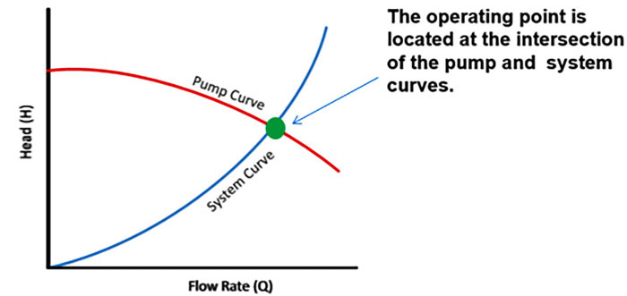 Image 1. The operating point is located at the intersection of the pump and system curves. (Images courtesy of ABB Drives and Controls)
System Curves
A system curve graphically defines the amount of head pressure required to move a fluid through a hydraulic piping system as a function of flow rate. Head, which is measured in meters or feet, is the maximum height (pressure) a pump can achieve. In wastewater applications this is the vertical lift from the inlet of the pump to the discharge of the pipe. Flow is measured in gallons per minute. The system curve is derived from the two major system-related aspects that a pump must surmount:- Static head: the fluid elevation (uphill) differences between pump supply and pump, and the pressure differences between pump supply and pump system
- Frictional head: the frictional impediment to the fluid flowing through the system caused by things such as the type of pipe, diameter of the pipe, flow regulating valves and fittings such as any elbows or tees in the piping route
Pump Curves
Typically provided by a pump manufacturer, a pump curve describes the relation between the flow rate and the head for the actual pump (essentially data about a given pump’s ability to produce flow against certain head). It is only good for one specific pump, with one impeller diameter, operating at one speed and has one best efficiency point (BEP). A pump operates where the pump curve and system curve intersect. As conditions change and the operating point moves along the pump curve, the pump efficiency changes.Popular Pump Control Methods & Their Inefficiencies
In examining the common methods water districts employ to match the pump performance to the system requirements, it is important to understand how pump curves relate to operating a pump at its rated speed. As head increases from the BEP, efficiency decreases as the operating point moves up the pump curve toward shutoff head. As flow increases (which means head has decreased) from the BEP, efficiency decreases as the operating point moves down the pump curve. If a valve is installed to restrict flow or use a bypass to restrict head pressure, the pump curve does not change and the operating point simply moves up and down the pump curve. Common pump control methods and inefficiencies include:- Oversize the pump: Run the pump at the rated speed but use a larger pump to maximize flow and head. This wastes energy because the pump is providing more flow and head than required.
- Add a throttling valve: Add a discharge valve to the pump to control flow into the pumping system. The valve adds more system resistance (friction), causing the operating point to move up the pump curve, wasting energy.
- Add a bypass valve: This allows water to flow back to the suction of the pump, decreasing system resistance and increasing flow from the pump, causing the operating point to move down the pump curve, wasting energy.
- Trim the pump impeller: This lowers the flow and head produced by the pump and generates a new pump curve. Once the impeller is trimmed, the ability to increase the flow delivered from the pump in the future is lost, and the pump efficiency decreases. The more trimming is done, the more inefficient the pump becomes.
Controlling Flow with a VFD
There is a common misperception that pairing a pump motor with a VFD simply moves the operating point up and down the pump curve. In reality, for every 0.1 hertz (Hz) of speed regulation, a new pump curve is developed, resulting in an infinite number of pump curves generated by varying the speed of a pump. But the system curve stays the same, so as speed is varied the flow in the pumping system is also varied, dropping the amount of frictional head pressure as flow decreases. The pumping system did not change, so the system curve is still valid as speed varies in the pump, with the operating point simply sliding up and down the system curve. In the majority of applications, pairing a pump motor with a VFD provides a pump curve that exactly matches the pump operating point the system requires at any time, controlling the flow without wasting energy or sacrificing efficiency. In friction dominated systems where the pump is at full speed and operating close to BEP, the pump will continue to operate near the same efficiency point as pump speed is decreased. The energy required by a pump can be calculated by Equation 1. If flow or head pressure is decreased, energy will be saved. Because the VFD exactly matches desired system design points, power consumed by the pump is minimized, improving overall pumping efficiencies. Pw = (flow x head) / 3,960 (assuming specific gravity of fluid is 1) Equation 1 In the case of an oversized pump, using a VFD allows for the use of a larger pump to meet future or periodic high flow requirements without wasting energy during the majority of operation. And unlike the limitations created by a trimmed impeller, the use of a VFD preserves the ability to increase the speed of the pump in the future when expanded flow and pressure are needed.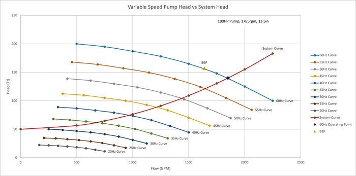 Image 2. Illustration of how varying the speed of a pump creates new pump curves for every new speed
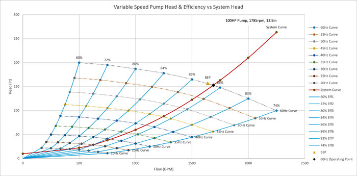 Image 3. Efficiency curves with variable speed in a friction dominated system. Notice how efficiency is held constant as speed is decreased in the pump causing the operating point to slide down the system curve.
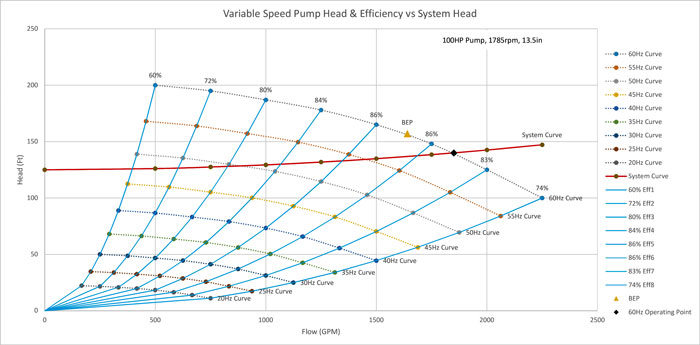 Image 4. Efficiency curves with variable speed in a static dominated system. Notice how the operating point slides across efficiency curves as pump speed is decreased.
 Protecting an Aging Pumping Infrastructure
As noted, the most prominently regarded benefit of variable speed pumping is energy savings, which is quite significant in many cases. There are additional benefits that positively impact system reliability that justify the use of VFDs, even where the energy savings factor alone may not be enough. Another major benefit of VFDs is in mitigating stress on an aging pump system infrastructure. In many municipalities where the piping system is old and decaying, a full voltage start of the pumps across the line could cause damage to pipes, pumps and motors, and increase expenditures required to maintain the system. The soft start and stop function that the VFDs provide prevents the violent start and rapid acceleration of inertia that occurs with a full voltage start while eliminating the electrical inrush to the pump motor, which can decrease a municipality’s total electrical demand, thus minimizing monthly electrical expenses. This minimizes the mechanical stress on the motor winding, pump bearings, shaft and impeller keyway. It also eliminates water hammer in the pump system, which is detrimental to an aging piping infrastructure.Achieving a Higher Efficiency
In some cases higher pump efficiencies can be achieved with the use of VFDs if the operating point of the system is to the right of the BEP. When slowing the pump down in systems that have a fair amount of static head, the pump can be operated at a speed that will operate at the pump BEP. Adding a VFD to a pumping system will not guarantee energy savings on every application. When evaluating the use of VFDs on the basis of energy savings alone, one must take into account specific energy. In short, specific energy can be defined as the cost to pump a given amount of fluid annually. This evaluation should take into consideration total system efficiency, annual gallons pumped by the system, cost of energy, pumping system characteristics, pump specific concerns and other criteria.Additional VFD Benefits
- Decreased vibration in the pump and pumping system when pump speeds are decreased to control flow versus using control valves
- Decreased noise as pump speed is decreased
- Increased seal life within the pump, as long as the pump operates in the preferred operating range (POR)
- Decreased net positive suction head required (NPSHr) as pump speed decreases with a VFD to allow sumps to be pumped to a lower level without causing cavitation within the pump
- Reduced potential of cavitation
- Fluid pressure drops as the fluid is split into separate streams as it enters different vanes of the impeller.
- If fluid pressure coming into the pump is at insufficient levels above the vapor pressure in the impeller, bubbles will result.
- As these bubbles travel up the impeller, pressure increases causing the bubbles to collapse. The pressure wave resulting from bursting bubbles is cavitation.
- The cavitation bubbles are small explosions that also release enough energy to create small pits in the impeller surface. Over time, these pits become larger causing excessive wear on the impeller, and ultimately failure.
