

Pumps require the right instrumentation to keep them running effectively. The instrumentation in a pump system includes all devices that measure and regulate the process. As fluid is moved through the pump, control devices monitor key measurement parameters such as pressure, temperature, flow rate and vibration. These devices protect the pump from damage and help optimize performance. They are strategically placed along the pump system to track process variables. Pump instrumentation can be integrated with the user’s control system, allowing any issues to be detected remotely. Choosing the right instrumentation is crucial, and many factors play into the selection process. Instrumentation is the eyes and ears of the pump, giving the user confidence that their system is operating correctly.
The Role of Instrumentation in Pump Systems
Types of devices
Pressure and temperature switches are essential to protect the pump from too high or low conditions by having the ability to switch the pump on or off. Sensors within these devices detect pressure and temperature levels—the baseline for understanding pump conditions. Other sensors include flow and vibration sensors, and another type of device is the pressure and temperature gauge. These display process variables and confirm if values are within the desired ranges. Flow meters are also implemented to detect valve positioning and potential blockages. The devices within a pump system work together to maintain pump functionality and avoid issues.
Device location diagram
Two common locations for instrumentation in a pump system are the suction line leading into the pump and the discharge line out of the pump. These locations give useful insight into the overall health of the pump. The suction line parameters indicate whether the flow and pressure leading into the pump is sufficient.
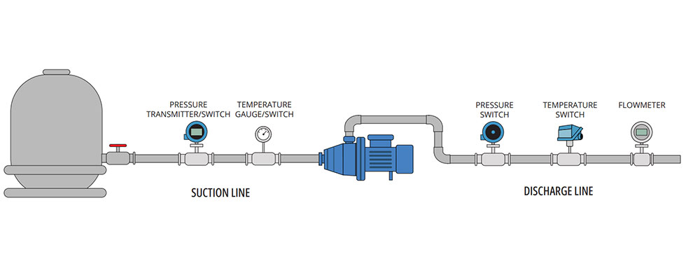
On the other side, discharge line parameters show if the pump is producing enough pressure or if there are any blockages. More key locations include the pump motor, fluid tanks and system piping. Image 1 shows a simple pump system layout with common instrumentation locations.
Device Implementation
Pressure and differential pressure
The purpose of a pressure switch, gauge or transmitter is to gain insight on the pressure levels of the media before and after it enters the pump. A pressure transmitter provides continuous measurement by sending a signal to the control system, while a pressure gauge gives local indication only. A pressure switch has the capability to shut the pump down if pressure becomes too high or low. It does this either by communicating with the control system, or directly if wired to the pump. There are also hybrid devices that operate as a pressure switch, gauge and transmitter all in one.
Pressure instrumentation used in a pump system can be seen in a water supply pump that feeds into a building. As water taps within a building open, the pressure sensor detects that pressure is decreasing. A signal is sent to the pump control system, causing the pump to speed up.
When building water usage decreases and the pressure rises again, the pump is told by the system to slow down. If there
is a leak, the pressure will suddenly decrease. Once it falls to a predetermined set point, the pressure switch will shut down the pump and activate an alarm.
Temperature
Temperature instrumentation in a pump system indicates pump productivity and is critical for safety and damage prevention. Similar to pressure devices, temperature sensors and gauges read the values of the media and communicate to a control system or present them on a local display. Types of temperature sensors include resistance temperature detectors (RTDs), thermocouples and liquid-filled mechanical sensors. When fluid temperature becomes too high or low, switches shut down the pump to prevent overheating or motor overload.
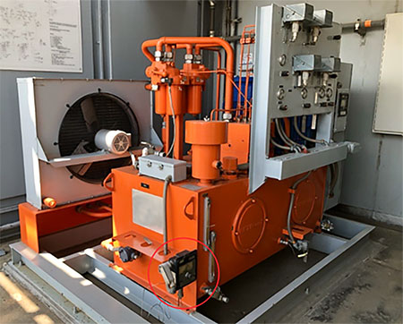
An example of temperature instrumentation being useful is on a lubrication oil pump. A temperature switch is used to monitor the temperature of lubrication oil and prevent pump damage. The temperature switch is placed on the inlet line of the system, and if oil temperatures become too hot or too cold, the switch will turn the pump off. If lubrication oil becomes too hot, it thins out and can be damaging to the pump and bearings due to lack of lubrication. On the other hand, if lubrication oil is too cold, the oil becomes too viscous and can overwork the pump motor while trying to provide the proper flow. This application and temperature switch are shown in Image 3.
Flow devices
While pressure and temperature are the main process variables monitored, flow devices are also important in maintaining the pump system. They measure the rate at which fluid is flowing through the system, typically in the piping along the discharge line. Flow meters are used to monitor pump speed and performance, and values indicate if there is cavitation or blockage.
Flow devices are useful in pump systems in wastewater applications, for example. A flow meter is used on the outlet side of the pump. If the flow rate decreases, the user may check for blockages or pump health. Additionally, a flow switch can detect a closed valve or blockage. Some pressure switches use plugged port features, which allow users to detect blockages or closed valves without needing a flow device.
Integration With Control Systems
Control systems commonly integrated with pumps are programmable logic controllers (PLC) and distributed control systems (DCS). After devices measure process variables using sensors, they must relay that information to a control system, which initiates a control action. This allows the user to oversee all key parameters and trend data, providing an understanding of the system’s condition.
The instrumentation works together with the interface to run a fully automated pump system by converting physical data into an electrical signal to send to the interface. The user can manage happenings within the pump remotely via the control system. Many users are deploying wireless communication technologies to transmit the process value so they can manage their pump operations remotely.
Instrumentation Selection
There are many factors that play into the selection of instrumentation for a pump system. The user must begin with knowledge of process conditions, safety requirements and the control system being used for system integration. It is important to know properties such as the operating pressure range, media temperature and ambient temperature. Fluid characteristics like viscosity and material compatibility are also helpful in instrumentation selection. Safety requirements to consider are voting logic, response time, safety integrity level (SIL) ratings and electrical ratings. When it comes to control system integration, the user must consider the type of output signal needed, communication protocols and signal reliability. Other important factors are technical approvals, compliances, installation requirements and cost. These all have a role in the unique instrument selection for a pump system.
Instrumentation works together with the pump and control interface to automate and communicate happenings within the system. Pump systems can have a wide range of applications with unique requirements. Whether a pump is used for wastewater treatment, the oil and gas industry or a renewable energy plant, they all require basic instrumentation to keep systems running properly. Pump instrumentation works with a control interface to fully automate the system, allowing users to maintain the pump remotely. A comprehensive understanding of the instrumentation can help users prevent system downtime and damage.
