Inherent arc hazards are often overlooked in medium-voltage AFDs
Eaton

The Fire Protection Research Foundation reports fatal injuries related to electrical incidents from 2004 through 2010 resulted in 1,494 fatalities, 29 percent attributed to direct contact with wiring, transformers and electrical components. From 2011 to 2013, 43 percent of fatalities were attributed to indirect contact and 54 percent attributed to direct contact.

There is a systematic approach to minimizing or mitigating the risk of electrical injury. The Occupational Safety and Health Administration (OSHA) Hierarchy of Controls (see Figure 1) outlines the following controls from highest level to lowest: elimination, substitution, engineering controls, warnings, administrative controls and personal protective equipment (PPE).

figure 1 osha
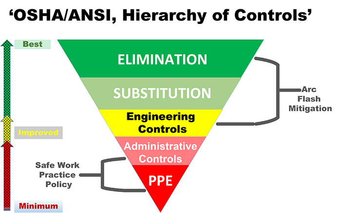
Figure 1. OSHA hierarchy of controls

Ideally, reducing the risk of injury with electrical equipment would involve eliminating the hazard altogether. Substitution, the second in the OSHA Hierarchy, allows different equipment to be used that is designed to reduce the risk of injury.

The equipment selected could be arc-resistant rated to protect personnel from arc flash and arc blast injury.

There are three distinct reasons why arc-resistant drives need to be considered when evaluating the risk of arc flash and arc blasts from internal arcing faults in medium-voltage adjustable frequency drives: system architecture, system impedance and system failure modes.

1. System Architecture

Many different manufacturers build arc-resistant equipment. This includes, but is not limited to low-voltage metal-enclosed switchgear, medium- and low-voltage motor control centers (MCC) and medium-voltage metal-clad switchgear.

Product safety has evolved to incorporate the Institute of Electrical and Electronics Engineers (IEEE) standard C37.20.7-2007, Guide for Testing Metal-Enclosed Switchgear Rated Up to 38 Kilovolts (kV) for Internal Arcing Faults.

This standard is widely adopted and builds harmony among vendors, end users and third-party certifiers. Switchgear and MCCs built and certified to this standard are prevalent in facilities worldwide.

Medium-voltage adjustable frequency drives (AFDs) are common in large industrial facilities and are often overlooked regarding the hazards associated with operating and maintaining such complex equipment. It is assumed there is no inherent hazard, but a proper evaluation must be performed. Medium-voltage drives comprise many interconnected power components operating in tandem. A medium-voltage drive should not be considered a simple add-on piece of equipment or switchgear. Manufacturers may provide a fully integrated or non-integrated solution with various drive topologies. Non-integrated solutions require the end user to select equipment such as feeders, power transformers, reactors or filters. Specific coordination is required between components to ensure adequate functionality and protection. Feeder options include load-break switches, fused contactors and power circuit breakers.

2. System Impedance

With medium-voltage AFDs installed in industrial areas with weak or soft utility power systems, it is important to understand how this affects the arcing current magnitude and duration. Equipment is type-tested and rated at a specific short-circuit current magnitude and duration. In many installations, the actual available short-circuit can be a fraction of the equipment rating. Also, arc-resistant equipment is given a third rating based on the arc-fault duration tested.

As an example, a 20 megavolt amperes (MVA) substation transformer rated 13.8 kV/4.16 kV of 8.5 percent impedance has a rated secondary current of 2,779 amperes and a theoretical maximum short circuit of 32.7 kilo amops (kA). However, if the utility available short circuit is only 10 kA, the transformer secondary short-circuit current is reduced to 16.4 kA; the utility impedance has limited the transformer secondary short circuit current.

Given most medium-voltage AFDs must comply with the IEEE 519 harmonic limits, manufacturers address this need with an isolation transformer or line reactance in the converter. Added line and converter impedances decrease the bolted fault and arcing fault currents. This can lead to increased fault clearing time from protective devices, which increases incident energy. The added impedances have actually caused an overlooked hazard.

3. System Failure Modes

Primary faults:
Care should be taken to understand the perspective arcing current magnitude and upstream clearing times of the protection equipment. It is critical to perform a system study and ensure that proper coordination is achieved. It is also important that the arcing fault duration does not exceed the equipment rating. System impedances can inadvertently increase incident energy if not addressed.

Transformer secondary faults
Medium-voltage AFD isolation transformers are complex and vary based on the converter topology. It is not unusual for these types of transformers to have four or more secondary circuits. Secondary fault current reflected to the primary side can be significantly lower than expected. This is due to the interaction between the primary and secondary circuits. This can cause protection coordination issues resulting in higher arc flash incident energy than anticipated. A complex model is required that is typically outside the capability of traditional power system analysis software. Transformer data and third party testing is necessary.

Converter faults
Some manufacturers do not incorporate fast acting semiconductor fuses into the AC to DC converter; these are “fuse-less” designs. When semiconductor fuses are provided and properly coordinated, this can reduce the available incident energy by decreasing the clearing time.

Another failure mode of power converters is the diode arc-back failure outlined in IEEE 551 Violet Book, section 8.7. When a diode loses its semiconducting properties, the current magnitude exceeds that of typical three-phase bolted faults by up to 2.73 times. If not accounted for in the design of the drive, this short-circuit peak current can result in catastrophic transformer failure and arcing faults resulting in significant enclosure damage.

DC bus faults
An arcing fault on the DC bus is difficult to model but can be estimated as a three-phase arcing fault on one of the transformer secondary circuits. If the rectifier fuses are supplied, they could reduce the fault clearing time. If fuses are not supplied, the line side protection would need to be analyzed based on the current reflected to the transformer primary. Also, in a distributed multi-pulse rectifier design, a fault may begin at a single secondary circuit, but then dynamically propagate to subsequent locations.

Inverter and output filter
Insulated-gate bipolar transistor (IGBT) based inverters and controllers respond quickly to short circuits. Testing on the load side of an inverter and output filter is necessary to ensure the drive controllers have built-in sensing and control circuitry to detect arcing faults, and have a fast enough response time to reduce or eliminate the arc fault incident energy.

Ionized gases
An arcing fault heats copper rapidly to near 35,000 F causing expansion and producing a pressure wave that has to be contained and directed away from personnel. The peak pressure wave occurs between 8 and 10 milliseconds after arc initiation. With drive configurations using forced-air cooling, a deflection means is necessary to prevent pressurized gases from exiting the intake vents, possibly toward a user. Louvers that close upon internal high pressure is a solution to prevent this scenario. Type testing as required by IEEE C37.20.7 has measures to detect non-complying internal arc fault containment.

Ionized gas from an arc fault is also the source for dynamic propagation. Switchgear and MCCs use phase barriers to reduce the likelihood of propagation and to allow fuses to clear the fault as intended. AFD designs incorporating stacked converters and inverter modules are vulnerable to propagating failures. An arcing fault in one module can easily propagate to an adjacent module, absent these barriers.

Conclusion

With so many different drive topologies it is easy to think of AFDs as a “black box” with no inherent hazards. However, by analyzing the failure modes within the drive, hazards related to arc flash are highlighted. There are many design controls that can reduce the associated hazards and, most importantly, rigorous third party testing and certification to verify those design controls.