
By sizing the pipeline correctly, you can reduce both operating costs and the time the pump needs to operate.
Engineered Software Inc.
04/02/2018
Editor’s Note: Dominik Fry is a member of Ray Hardee’s team at Engineered Software Inc. He contributed to this column.
While instructing new engineers in the industry, I always stress the importance of understanding how the individual items of a piping system work together. While each engineer may be responsible for a separate portion of the process, all the pieces must ultimately work together in balance.
I ask course attendees what they do at their facility and what they hope to get out of the experience. Each attendee has a specific topic of interest, but whether it is a process engineer, reliability engineer, maintenance engineer or anyone else involved in the process, an overall goal is to improve the operation of the pumps.
One interesting topic that came up recently involved large temporary pumps in the desert. I inquired how large the pumps were. The engineer said they were mounted on a semi-trailer, so they could be easily repositioned. They were equipped with a second semi for the diesel electric power supply. Even though the operation was in the desert, the rainfall would run off the ground and result in flash floods that could quickly collect and cause a disruption in production.
During the training when I discussed system static head, I emphasized that the static head of the dewatering system amounted to the difference in elevation between the water level at the bottom of the mine and the end of the discharge piping.
When we covered the material on pipeline sizing, the engineer asked why we needed to perform this calculation. He said his rule of thumb was to size the discharge pipe to that of the pump’s discharge flange.
For example, if the pump’s discharge nozzle was 6 inches, he would use a 6-inch pipe for his discharge header. This column will discuss why this rule of thumb may be costly.
The System
A piping system is made of three elements: the pump elements that add all the fluid energy, the process elements that make the product or provide the service and the control elements that improve the product quality. Image 1 shows the piping system details.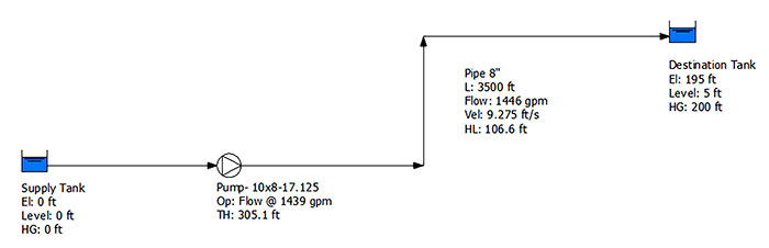 Image 1. Layout of the example piping system showing the pump and process elements. Control of the system is achieved by turning the pump off when not required. (Images courtesy of the author)
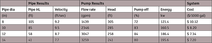 Table 1. System operation with various pipe diameters along with the resulting cost per 1,000 gallons pumped
Totaling the Cost
First, we will look at the system with an 8-inch nominal size discharge pipe. This is the same diameter as the discharge flange on our pump. The resulting flow rate through the system is 1,438 gallons per minute (gpm), resulting in a head loss of 105 feet of fluid in the discharge pipeline. Adding the head loss of the pipeline to the system’s static head of 200 feet results in a head of 305 feet for the process and control. The pump curve shows that a flow rate of 1,438 gpm through the pump results in a head of 305 feet. The balanced flow rate through the system is such that the head produced by the pump is equal to the head consumed by the process and control elements. Next, we will calculate the power cost needed to pump 1,000 gallons of water at 60 degrees Fahrenheit (F) through the 8-inch pipeline using Equation 1. While the cost of energy varies widely throughout the United States, the average is roughly 12 cents per kilowatt hour, which is what we will use in these calculations. In reality, some areas of the country may be double this cost, or even more when the power is produced on-site through diesel generation.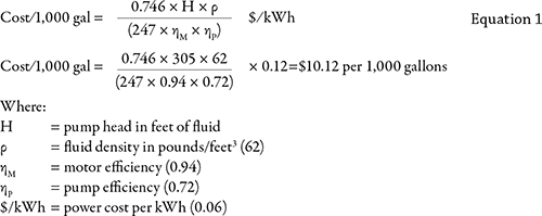 Table 1 shows how the system operates with various pipe diameters along with the resulting cost per 1,000 gallons pumped. The table demonstrates the interaction between the various elements found in a fluid piping system. As the pipe diameter increases, the head loss in the pipeline decreases along with the fluid velocity. With lower pipeline head loss in the larger pipeline, more of the pump’s energy can be used to move fluid.
As the flow rate increases in the pump, the head produced by the pump decreases, as demonstrated on the pump curve (see Image 2). In addition, changing the flow rate through the pump varies the pump efficiency.
Table 1 shows how the system operates with various pipe diameters along with the resulting cost per 1,000 gallons pumped. The table demonstrates the interaction between the various elements found in a fluid piping system. As the pipe diameter increases, the head loss in the pipeline decreases along with the fluid velocity. With lower pipeline head loss in the larger pipeline, more of the pump’s energy can be used to move fluid.
As the flow rate increases in the pump, the head produced by the pump decreases, as demonstrated on the pump curve (see Image 2). In addition, changing the flow rate through the pump varies the pump efficiency.
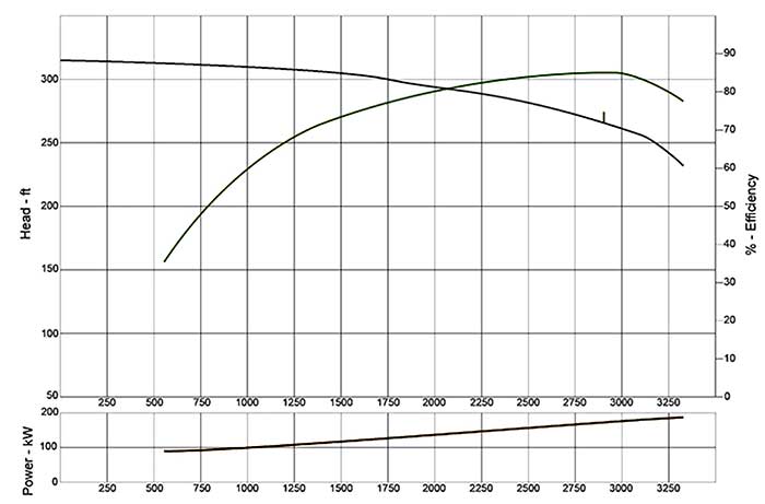 Image 2. Manufacturer’s supplied pump curve for the pump used in the example system.
Pipeline Sizing Parameters
Rather than performing a detailed cost optimization for sizing pipelines, companies have developed piping specifications based on the process fluid being handled. These specifications have been developed over time based on the company’s needs and experiences. A chemical process plant, for example, will typically have many pipe specifications for the various process fluids they handle, while an industrial plant may have a few specifications for the cooling fluids and transporting fluids needed for the process. The Crane Technical Paper 410, Flow of Fluids through Valves, Fittings and Pipe, provides recommended fluid velocities for general service applications, pump suctions and municipal applications. The pipe fluid velocity range for general service applications is between 4 and 10 feet per second. As demonstrated in Table 1, the 8-inch diameter pipe is on the high side of the recommended velocity range.How Pump Manufacturers Arrive at a Flange Diameter
Some end users may ask why the pump manufacturer does not size the pump discharge flange for the recommended pipe diameter. There are a variety of reasons for this. The larger the discharge flange, the greater the pump footprint. Because one of the major costs of the pump is the pump case, a larger flange size would increase the size and cost of the pump. The distance the fluid travels from the impeller tips to the discharge flange is short compared with the discharge piping. As a result, higher fluid velocities within the pump can be used because of the limited head loss due to the moving fluid and the stationary pump. To minimize the number of castings required to meet its customers’ pumping needs, a manufacturer may trim the impeller or design the pump to operate at various synchronous speeds. For example, the manufacturer supplying the pump in the example system makes it available with impellers ranging from 12 to 17.125 inches. In addition, the pump is available with both 1,200- and 1,800-rpm drives. The variation in the pump impeller diameter and synchronous speed affects the flow rate through the pump. Choosing the pump discharge pipe based on the pump discharge flange size is not recommended practice. As we saw in this application, sizing the pipe diameter to match pump discharge diameter resulted in a greater unit cost for pumping the process fluid. In addition, the smaller pipe diameter resulted in lower flow rates through the system. By sizing the pipeline correctly, you can reduce both operating costs and the time the pump needs to operate. In this example, proper pipeline sizing helps pump water faster, more economically and more efficiently, which ultimately extends the life of the pump and improves the entire operation.
To read more Pump System Improvement columns, click here.
