Energy reduction and low maintenance add up to cost savings.
Dynamatic

Water reclamation facilities are subject to a wide range of influent flow rates. They must be designed to operate at a peak design flow, required during wet weather events, but also must operate efficiently and reliably at significantly reduced flow rates during ordinary operation. Accordingly, many pumps in such a process must produce an often-wide spectrum of flow rates.

A simple solution is to throttle the output of the pumps with a regulating valve, controlling flow in much the same way that adjusting a faucet reduces flow in household water systems. However, when pumps are large enough to require tens or hundreds of horsepower (hp), this method wastes unacceptable amounts of energy.

Even though flow can be controlled accurately, throttling the pump discharge usually results in reduced flow but almost no reduction in the required shaft hp to drive the pump.

The pump is forced to operate at higher system head to reduce the flow, not at or near its best efficiency point (BEP). In addition to increasing the energy required to maintain the necessary flow and pressure, this can lead to early mechanical failure of the pump.

Pump load as a function of speed
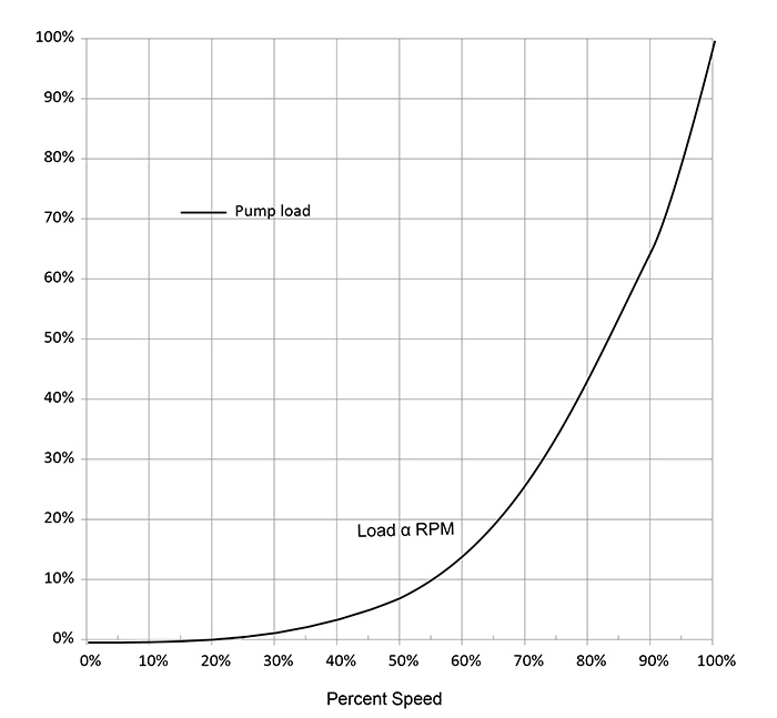
Figure 1. Pump load as a function of speed (ideal pump). (Graphics courtesy of Dynamatic)

Variable speed pumping has long been recognized as a strategy to reduce energy costs. The rationale is somewhat intuitive: if a pump can be operated at a reduced speed when demand is low, it should be expected to consume less power. This is especially true of rotodynamic (centrifugal) pumps. The familiar Pump Affinity Rule holds that shaft power required by the pump diminishes in proportion to the third power (cube) of the speed reduction. The ideal case is illustrated in Figure 1.

In most real-world applications, a pump will not deliver a useful rate of flow below a certain speed, usually 75 to 80 percent of rated speed. This is because the pump’s discharge pressure diminishes as a function of the square of speed, and quickly drops to equal to or below the system static head. Therefore, this point becomes the zero-flow point, and the pump delivers its full spectrum of flow between this point and full speed. If the pump is equipped with a check valve, it will open when the pump reaches this speed point and will close below that point (Figure 2).

Pump load as a function of speed
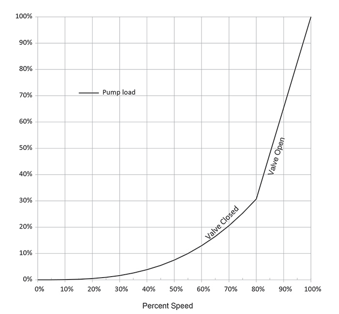
Figure 2. Pump load as a function of speed (real-world example)

Operating the pump at variable speed not only takes advantage of this phenomenon, but allows the pump to remain at or near its BEP. Compared to flow control by throttling the discharge, pumping at variable speed saves considerable energy, and thus the associated cost. In the example shown, if the average demand calls for a speed reduction to 90 percent, the pump shaft horsepower is reduced to approximately 65 percent of rated horsepower. By contrast, throttling the discharge to control flow would have little or no effect on shaft hp.

Any method to control pump speed will achieve these results. While some engineers immediately think of variable frequency drives (VFDs) for variable speed pumping, eddy current drives deserve strong consideration.

Cross section of an eddy current drive’s internal components
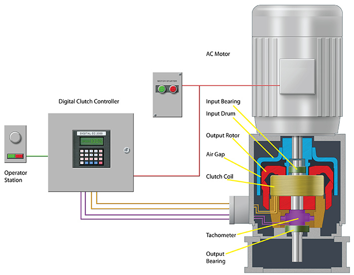
Figure 3. Cross section of an eddy current drive’s internal components

Unlike VFDs, which function by converting electrical power to cause the motor to operate at variable speed, an eddy current drive is an electromechanical torque conversion machine. It is driven at constant speed by an electric motor selected for the maximum expected pump rotations per minute (rpm). The motor drives a cylindrical member called the drum (Figure 3, shown in blue).

The electromagnetic rotor (red) turns on a separate output shaft, concentric and within the drum. A DC excitation current is provided to the magnetic coil (yellow), which enables the rotor to develop torque in proportion to the excitation current. By controlling the excitation current, the machine functions as a reliable and accurate VFD.

For the relatively narrow speed range required by most rotodynamic pump applications, the losses developed in the eddy current drive are comparable to those seen in VFDs, and, as noted above, a reduction in power consumption is achieved. The eddy current drive will have some additional advantages in the form of avoided losses:

  • The motor draws its power from the source at a clean, full voltage, full frequency, with no induced harmonic currents. Therefore, there are no additional I2R losses in feeder circuits, switchgear, transformers, etc. There are no requirements for harmonic filter devices or reactors, which would contribute to total losses if they were needed.
  • The motor will not experience elevated losses due to any harmonic currents, as it operates on sinusoidal power, for which it is designed.
  • There will be no need for additional cooling to the motor. It runs at full speed and benefits from a full flow of cooling air, regardless of pumping demand.
  • There is no need for auxiliary cooling or air conditioning. Most of the eddy current drive losses are a result of slip in the rotating machine, and its location is normally well suited to absorb and dissipate the associated heat.

These avoided losses contribute substantially to the overall pumping system efficiency, and should always be evaluated when considering a variable speed pumping system.

A major motive in seeking better efficiency is the expectation of reduced operating cost. Water reclamation agencies owe it to their constituents to use the ratepayers’ money wisely. For that reason, maintenance, operation and replacement costs should also be considered, though not strictly a matter of efficiency. Eddy current drives are well regarded as a reliable, long-term variable speed solution.

Like the motors that drive them and the pumps they drive, eddy current drives can be expected to remain in service 40 years or more with simple and inexpensive maintenance. Lubricating two or three bearings and changing carbon brushes are the only scheduled maintenance.

When repairs are needed, local service organizations are usually capable. Controllers are easily repaired with readily available parts. This is important to note, as early or frequent replacement of failed or obsolete equipment can quickly negate any cost savings from reduced energy consumption.

Conclusion

Saving money will probably always be the primary motivator in seeking better efficiency. However, as more communities and local governments desire to reduce CO2 emissions, reduced electrical consumption is recognized as a means to achieve a substantial reduction. Most agencies consume power generated by fossil fuel (coal or natural gas).

According to the U.S. Department of Energy, 1 kW-hr of electrical consumption is the equivalent of:

  • 1.5 pounds of CO2 from a coal-fired power plant, or
  • approximately 1.7 miles driven in a typical automobile

Second only to aeration, pumping applications are the largest consumers of power in a typical water reclamation plant. Seeking more efficient pumping systems is a popular and effective means of reducing costs, improving processes and cutting greenhouse emissions.

To read other Efficiency Matters articles, go here.