In the grand scheme of complicated industrial parts that make up complex operations, couplings may seem like simple components in comparison, but they often tell the story of what is happening across the entire drivetrain.
In aftermarket environments—where equipment history is mixed and installation practices are broad—couplings can be both forgiving and revealing. They absorb misalignment and shock, and if they fail, it often points to deeper issues such as poor alignment, thermal growth miscalculations or unexpected spikes in torque. Diagnosing these problems may seem confusing, but understanding these failure modes and how to prevent them is essential for reliability and control.
Why Couplings Could Fail
Most couplings are designed for long and strenuous operations, but that assumes operation within their ideal torque and misalignment limits. However, pumps and motors can experience stress from imperfect installation, foundation settling, pipe strain, thermal movement and many other small nuances from lack of proper servicing. Add in transient process upsets or frequency drives, and the coupling may be pushed beyond its design envelope. These conditions make stress difficult to quantify holistically and service life hard to predict. When a coupling fails, it is rarely an isolated problem, as the cause is likely a symptom of something much larger than a single component.
Angular Misalignment: The Silent Killer
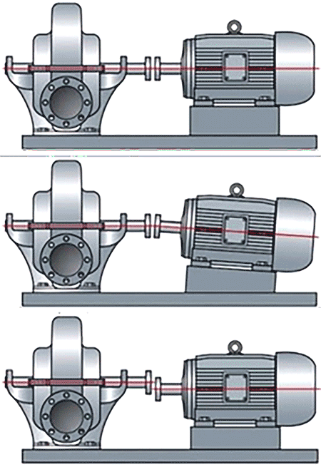
Angular misalignment occurs when the driver and pump shafts intersect at an angle rather than sharing an ideal, straight axis. In disc couplings, this condition concentrates bending stress near the outer discs and adjacent to bolt holes, which is where fatigue cracks often begin. Symptoms of this often include elevated axial vibration at multiple harmonics and a phase shift across the coupling of roughly 180 degrees. Over time, radial vibration may increase as the disc pack begins to unravel.
Preventing this devastating chain of events through angular misalignment starts with thorough alignment practices. Measuring both offset and face runout is critical, because the angularity of a shaft is the direct sum of these two factors, and they can even differ between ends. Thermal growth must also be considered—either through hot alignment or validated through cold-to-hot offsets. Additionally, soft-foot checks and pipe strain assessments should be a part of every alignment scope. Ideally, the coupling should operate within about 10% of its maximum angular rating to help ensure safe, long-term reliability within a system.
Axial Misalignment: When Spacing Goes Wrong
When heavily considered, axial misalignment is all about spacing. If the coupling flanges are too close or too far apart, the coupling operates under tension or compression, adding stress and load to the bearings.
Symptoms include fluctuations in motor current, elevated thrust bearing temperatures and axial vibration that pulses as the rotor thrusts in and out of position. Visual inspection often reveals cracks near bolt holes on both sides of the disc pack as mentioned above.
In order to prevent axial misalignment, it is important to verify the correct spacing against the coupling drawing and confirm the total axial capacity. Magnetic center checks are essential for motors, as is ensuring proper equipment validations. Thermal growth calculations should also be revisited to ensure the coupling is installed in the correct prestretched position conditions (if specified). As with most systems (and similarly stated above), operation within 10% of the axial rating is a good rule of thumb.
Torque Overload: An Unpredictable Danger
Unlike the misalignment issues discussed so far, torque overloads are usually sudden and event-driven. A process upset, liquid slug, electrical fault or emergency shutdown can all create torque spikes that exceed the coupling’s capacity. These types of failures are often instantaneous, leaving behind buckled disc packs and sometimes deformed flanges. Audible noise during equipment yielding and abrupt changes in vibration signatures are both common indicators of such an event.
The best defense against torque overload is simply preparation. After any suspected overload, inspect for crack initiations and replace coupling elements immediately. Review the application’s service factor and consider sacrificially designed parts, like shear spacers, for high-risk environments. Operational history—event logs, alarms and current traces—should consistently be analyzed to help identify root causes and prevent recurrences.
Torsional Oscillation: The Danger in Harmonics
Torsional oscillation is a vibration-based torque phenomenon that occurs when the system’s natural frequencies align throughout the powertrain components. Variable frequency drives are frequent culprits, introducing harmonics that excite torsional modes.
Synchronous motors can also trigger oscillations during frequent starts. Detecting torsional issues without torque measurement is difficult, but fractures in the center of disc links and fretting at the clamping areas are strong telltale signs of this occurring. As this is more of a unique problem, preventing it requires more of a system-wide approach. Review torsional models and tune coupling stiffness and inertias to shift away from critical speeds within the specified operating ranges. Torque monitoring can also provide valuable insight into both the steady-state and transient conditions of the components. The system’s drive parameters—such as ramp rates and carried frequencies—should also be evaluated for their impact on torsional behavior.
Improving Reliability in Pipeline Injector Pumps
The effectiveness of this advice can best be summarized through a brief look into an example set around pipeline injector pumps. These pumps are vital for moving crude oil from well sites into feeder pipelines. They also often operate on custody-transfer skids in remote locations where certain alignment practices can be inconsistent. In one application, rigid grid-style couplings were originally used to connect pumps to electric motors. While strong, these couplings required tight alignment tolerances that were rarely achieved in the field. The result was severe misalignment, elevated shaft stresses and even entire pump shaft failures. Maintenance crews faced long coupling changeouts and frequent seal replacements, adding to their costs and downtime.
The solution was flexible elastomeric spacer couplings. Unlike their standard rigid couplings, elastomeric couplings provided four-way flexing action, absorbing angular, parallel and axial misalignments as well as end float. The spacer design allowed for quick “drop-out” sleeve replacements without disturbing the pump and motor alignment—a major advantage for this remote site.
The results of this change were significant. Misalignment tolerances improved, reducing shaft and seal failures. Shock absorption damped torsional peaks and vibrations, and maintenance times were reduced across the board. With no lubrication required, crews avoided grease-related contamination and upkeep as well.
Best Practices for Success
Preventing coupling issues starts with a holistic view and understanding of a system. Alignment should include soft-foot checks, base flatness verifications and pipe strain assessments with rechecks for connections. Thermal growth must be accounted for, and torque integrity should be maintained through proper fastener patterns and hardware inspections. Service factors should reflect actual operating conditions, including starts, stops and variability. Similarly, condition monitoring—vibration, temperature, motor current and torque—provides operators and engineers with early warning signs of developing issues, which can help guide corrective action instead of reactive action.
While couplings may be passive components overall, they play an active role in a system’s reliability. By understanding common failure modes and applying preventative measures, operators can extend equipment life, reduce downtime and improve overall safety.
In the aftermarket, where variability is often normal or expected, coupling selection and installation discipline are critical. Whether it is mitigating misalignment, preparing for torque events or tuning for torsional stability, the right approach can transform couplings from potential weak links into strong points in a drivetrain.