There are numerous factors to consider to ensure the best performance with this technology.

One of the greatest advantages of a progressive cavity (PC) pump is that its flow rate is determined solely from the pump speed. The PC pump exhibits pump flow that is linear and repeatable, like an ideal metering pump. These pumps are unique because their starting torque is often greater than the operating torque during operation, but this characteristic creates a challenge when using variable frequency drives (VFDs) with PC pumps. This article will help with better selection of VFDs for most PC applications.

VFD Characteristics

Constant torque (CT) VFDs are used in applications where there is a linear relationship between power required and equipment speed. Variable torque (VT) VFDs are used when the required equipment power is not linear with respect to speed, like centrifugal pumps and fans.

Sensorless vector drives are becoming the preferred option for drives. This technology recognizes many factors that influence drive/motor performance, and it monitors them continuously to optimize performance and minimize power requirements.

For drive selection, note the VFD is a purely electrical device. Therefore, the selection is determined solely by voltage and current capability. The advertised horsepower (HP) is stated for the convenience of being similar to motors. The continuous rating should always be compared to the motor’s maximum amperage. The VFD’s overload capability in percent is a multiple of its maximum continuous current and not the motor’s full-load amperage. Only CT or sensorless vector CT should be used with PC pumps.

Electric Motor Theory

For the purpose of simplicity, assume that an electric motor is constructed of three electromagnets (stator) and the rotor—a metal that is attracted or repelled by the electromagnets. The magnetic field created by voltage and subsequent current causes the rotor to chase the magnetic field. When the rotor cannot keep up with the magnetic field, the motor draws high current.

The motor draws the most current when it is starting. The peak current the motor produces is often referred to as locked-rotor current. This locked-rotor current determines the maximum starting torque the motor will produce. It is usually a multiple of full-load current that ranges between 1.5 to 6 times the motor’s full load amps (FLA). This surge of current is what a PC pump relies on to be able to overcome the pump’s starting torque. Factors that have the potential to limit the motor starting torque include a conductor that is too small or too long, a circuit breaker that is too small, or minimal VFD overload capability.

A motor’s maximum starting torque is directly proportional to the current that it can absorb for a short period of time. The more it can absorb, the more torque the motor can produce.

When starting a motor across-the-line, this is only limited by conductor sizing. The VFD acts like a filter between the line and the motor. The filtering limits the amount of current based on the VFD’s design.

Most modern-day VFDs have this overload capability of 150 percent for 30 seconds and 180 percent for 5 seconds. Some can even handle 200 percent for short periods. The percentages are in relation to the maximum continuous current rating of the VFD, which is found on the nameplate.

Preparing VFD Operation

Selecting the PC pump involves experience and knowledge of the product and application. After selection, the starting torque, running torque and pump revolutions per minute (rpm) range are known entities.

Considerable thought should be given to selecting the gearbox ratio with respect to the rpm range of operation when using a VFD. It is beneficial to choose a gear ratio that is as high as possible and places your maximum VFD frequency close to 85 hertz (Hz) because a PC pump requires greater starting torque than running torque.

Comparing horsepower required for pumpsFigure 1. Comparing horsepower required for pumps (Graphics courtesy of SEEPEX)

Increasing the gear ratio gives the mechanical advantage by requiring less HP to generate the required torque. Selecting gear ratios in this manner can mean substantial power savings (see Figure 1).

An example of the potential effects of different gearbox ratios for the same pump
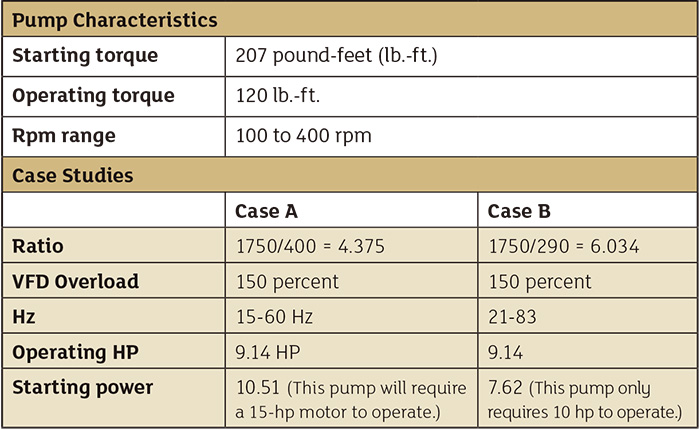
Table 1. An example of the potential effects of different gearbox ratios for the same pump

Consider the example in Table 1. Both Case A and Case B will work for the hypothetical application; however, Case B will have no issues starting using a motor two-thirds the size of Case A (see Figure 2). Case A will require more motor horsepower and starting torque to start the pump. The initial capital cost savings and power saving over ownership can be large.

Examining starting torque capacity
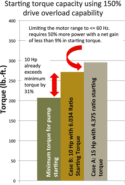
Figure 2. Examining starting torque capacity

VFD Parameters of Interest

Most VFDs have multiple parameters that can assist in situations where the starting torque is marginal. Some motors respond better to these changes than others; however, they should be checked as soon as there is an issue with starting the pump. Below is a list of these parameters, along with descriptions and advice:

Acceleration/deceleration time: This is the time period the VFD will take to increase or decrease speed from current speed to a new speed. It is a filter that will help limit the maximum amount of current generated during starting. This value is usually listed in seconds. Appropriate values range from 1 to 15 seconds. Shorter time allows more current to be produced, plus more torque and heat. Values from 3 to 7 seconds usually meet most applications without creating unnecessary mechanical stress.

Starting overload capability: In some drives, you can adjust this parameter to purposely limit 
the maximum current the drive will use to start the motor. In 
most cases, this should be left at factory settings, which are usually drive maximums.

Carrier frequency: Carrier frequency controls how often the voltage is modulated in the waveform. The most noticeable effect of raising the value is lessening motor/VFD whine as it passes outside of the range of human capabilities.

Increasing carrier frequencies increases motor thermal stress and sometimes reduces the maximum current capability. The rule of thumb is to leave this at the lowest value and only raise it if you have the extra capacity and auditory restrictions that you cannot 
meet otherwise.

Motor overload: This parameter is usually in the form of a percentage. Taking the full load amperage from the motor’s data-plate and multiplying by 100 and dividing the result by the VFD’s maximum continuous current rating gives the correct percentage. In most cases, the possible values range from 30 to 100 percent.

Motor overload type: Motor overload type usually has two options. One will be speed compensated and the other will be non-speed compensated. Speed compensation should be used whenever the motor fan speed is proportional to motor speed (non-blower-cooled). Non-speed compensated should be used in instances where the motor is cooled by a fan that does not change speed according to motor speed (blower-cooled).

Fixed boost: Fixed-boost parameter is rarely needed and almost always overused. This parameter sets the drive power’s minimum voltage. As we stated before, the voltage in a constant torque application should be in a linear relationship with speed. This parameter will override it at low speeds and not let the voltage fall below the preset value percentage. For example, if the parameter was set to 40 percent, a 460 VAC drive could not lower the voltage below 0.40 times 460 VAC or 184 VAC. The problem with the increased voltage is it will only temporarily help in starting, but always contribute to the motor overheating. Always keep this parameter at 0 percent. If the need arises to change it, check, check and recheck other parameters. Otherwise, this may be creating another problem.

Drive mode: The available parameters for this selection will vary according to the drive manufacturer and drive capability. In all cases, it should only be set to one of two selections. The first selection would be “constant volts/Hz,” which would be for drives that do not incorporate vector control capability. The other option will be “vector speed CT” control for 
drives that incorporate vector control capability.

Motor rated voltage: This sounds trivial, but this cannot be stressed too much in the world of dual-voltage motors. The drive voltage must be the same as the motor voltage, and the motor must be appropriately wired for the same voltage. Additionally, this parameter should be set for that same voltage.

Motor rated current: This parameter must be set to match the motor nameplate full load current in amperes.